NicePants42
Partition Master
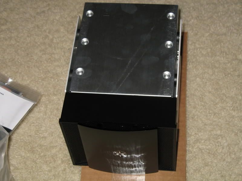
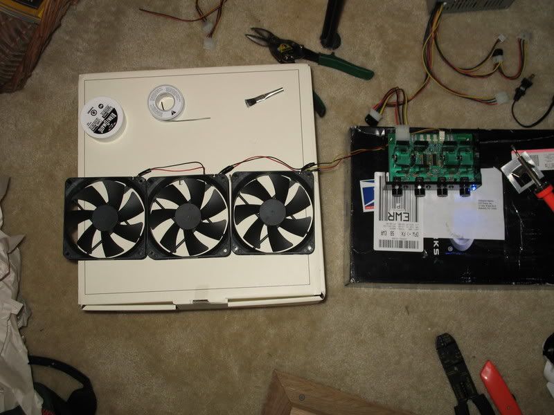
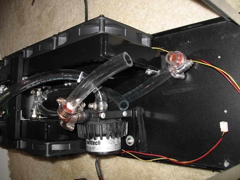
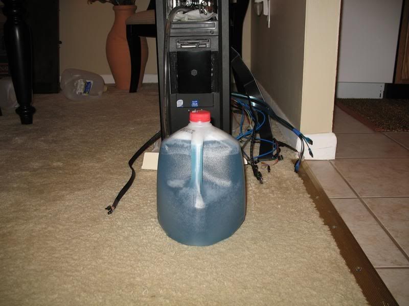
Some test assembly
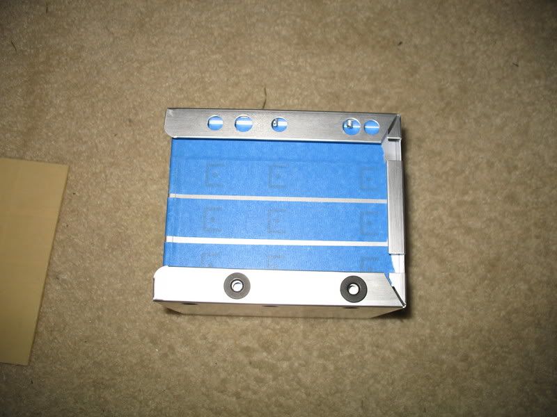
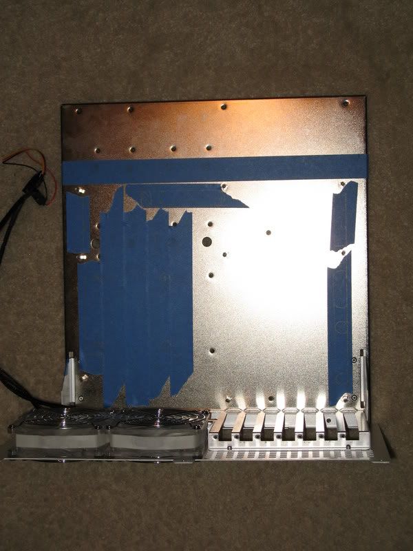
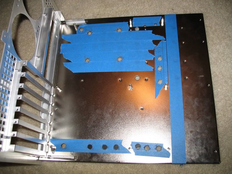
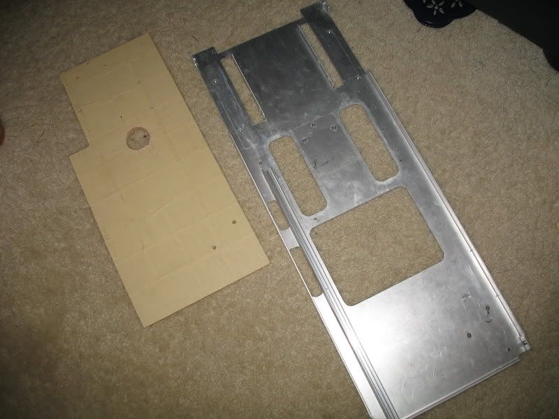
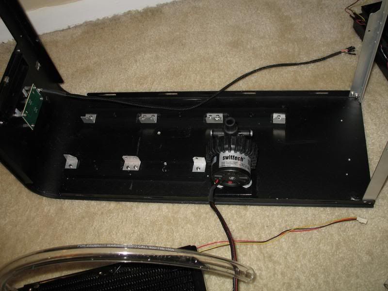
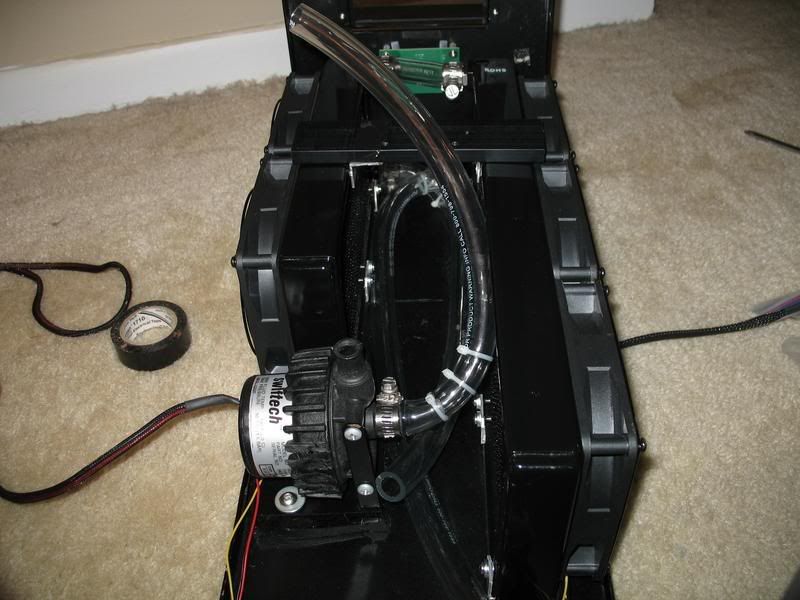
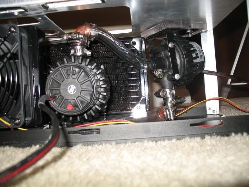
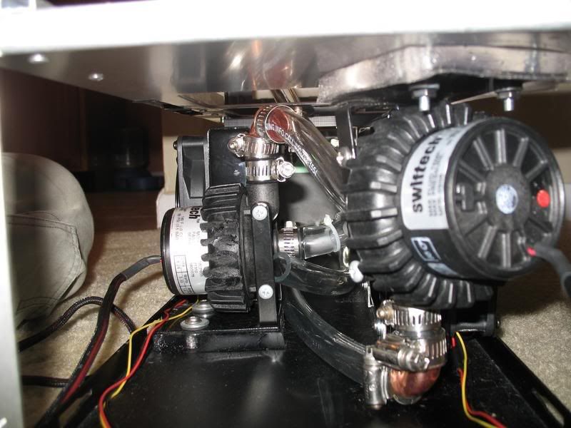
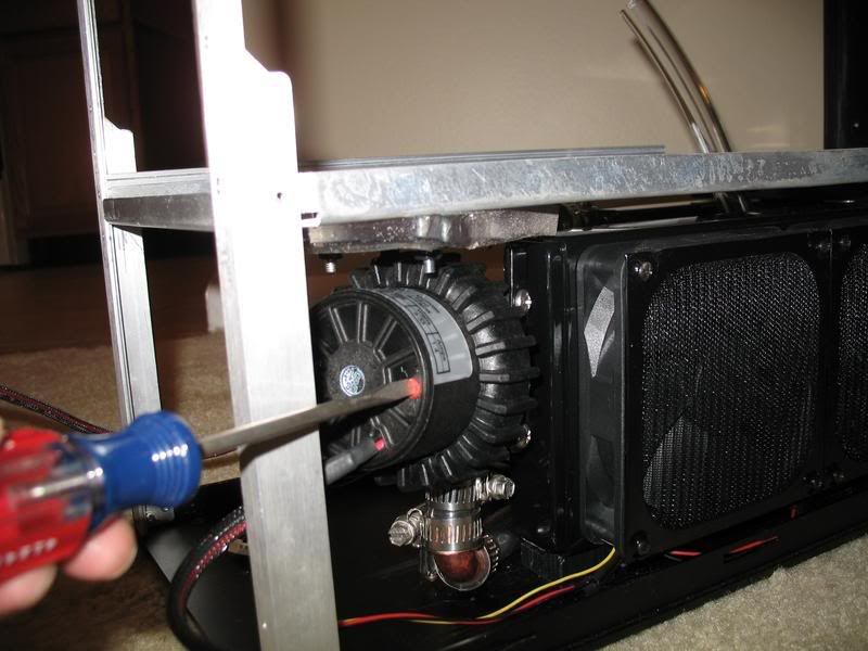
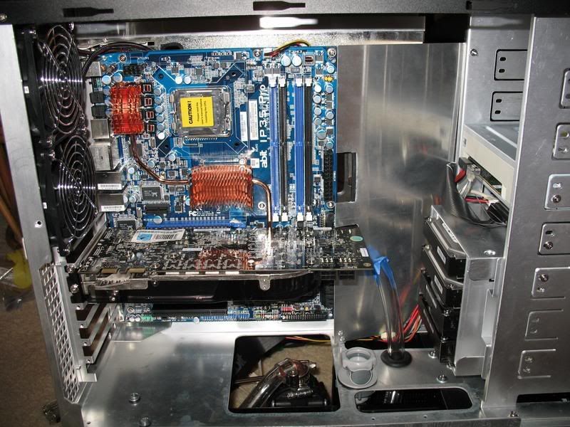
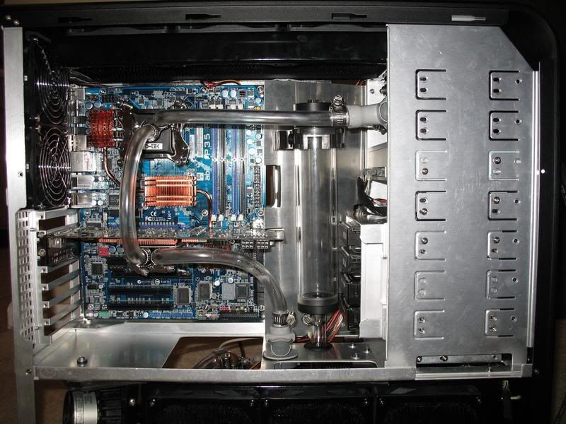
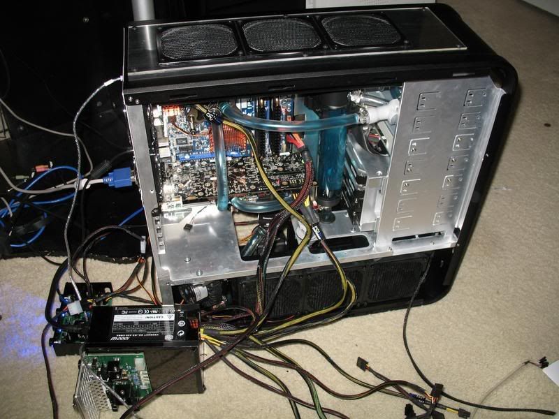
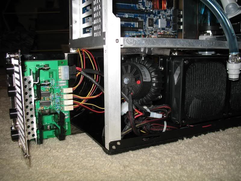
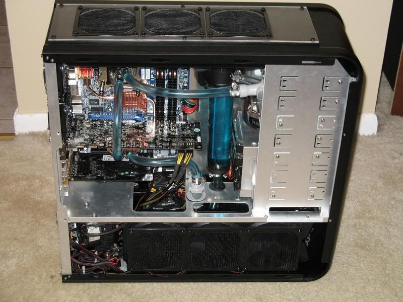
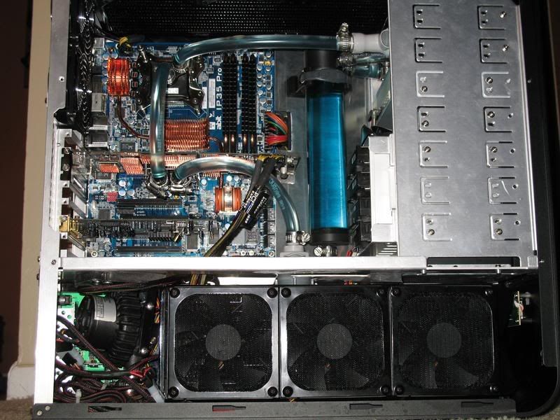
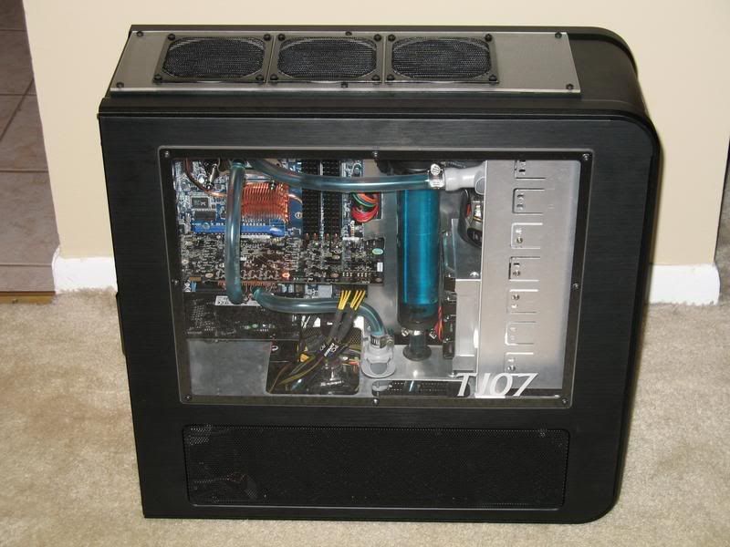
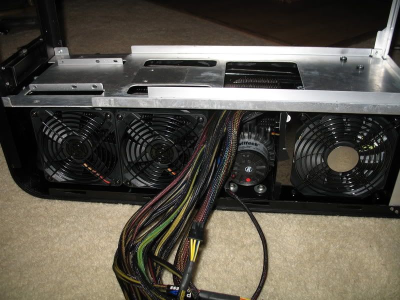
At this point the lower part of the case is pretty well taped out. Here you can see that assembly is completely feasible.

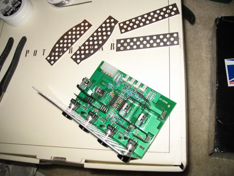
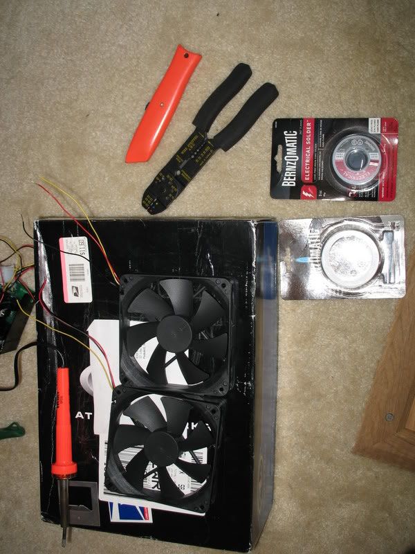
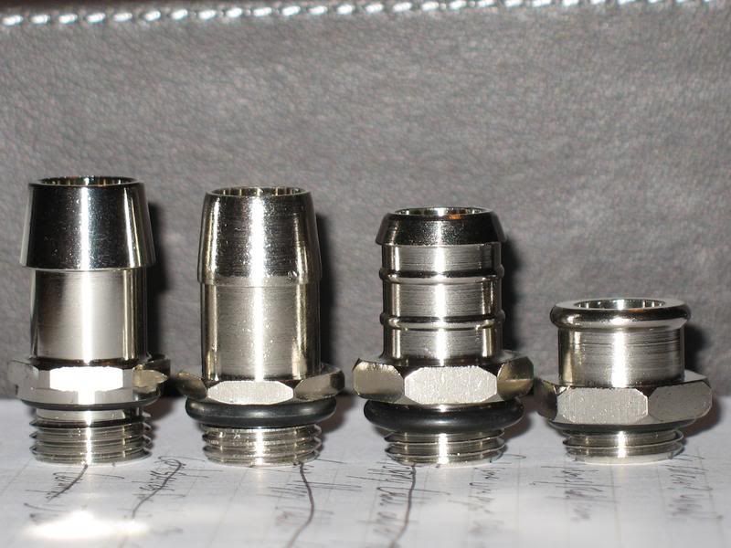
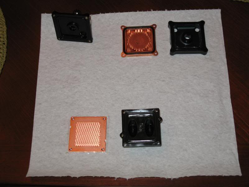
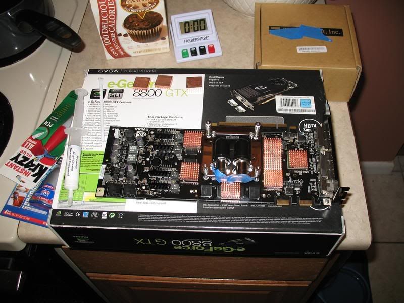
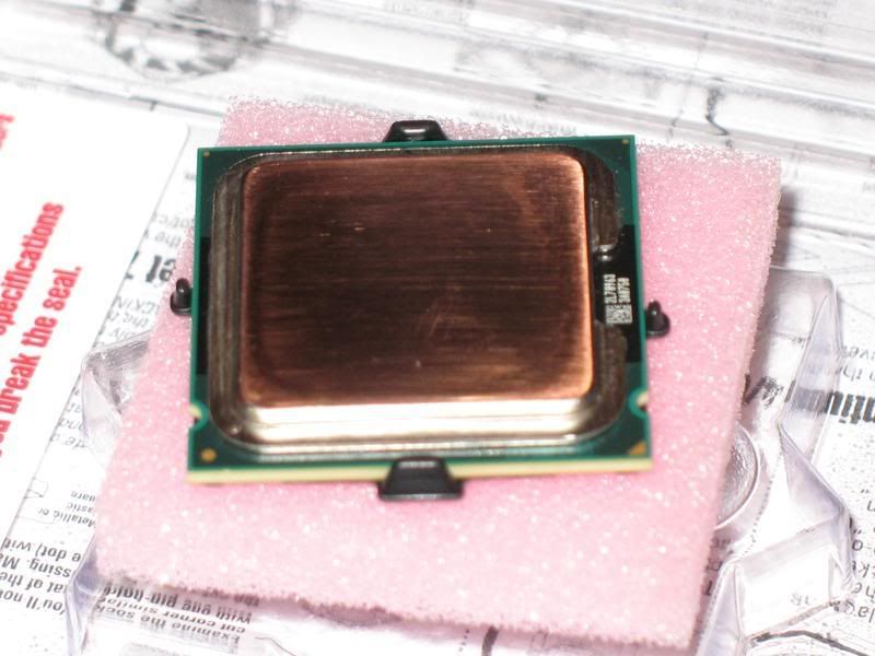
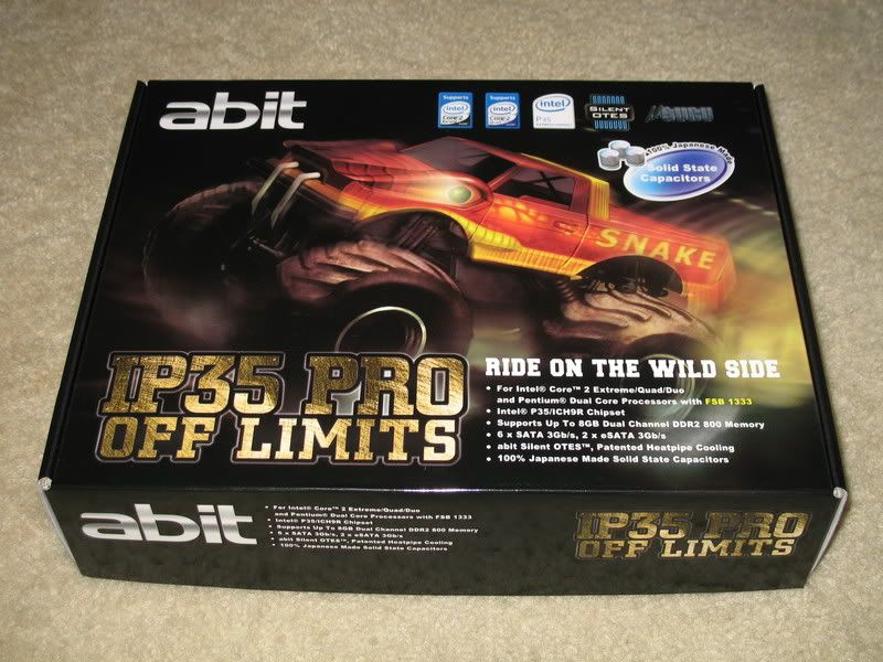
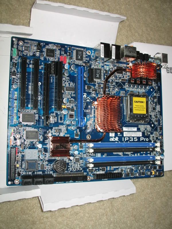
So I figured I'd try to assemble the top portion and find out what still needs to be done up there. It was also an excuse to open up some hardware.
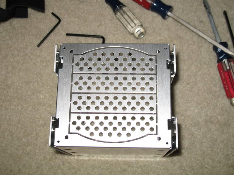
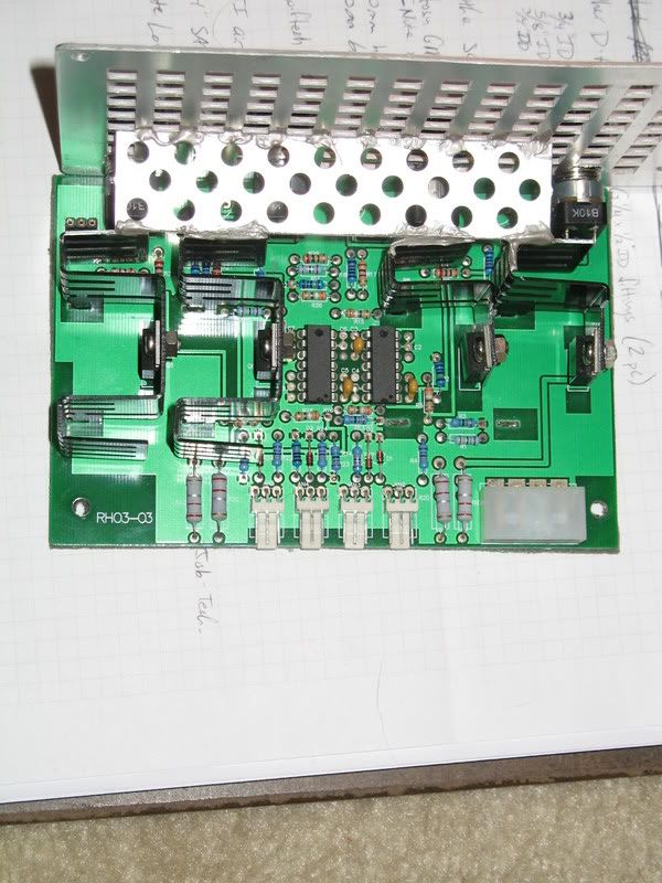
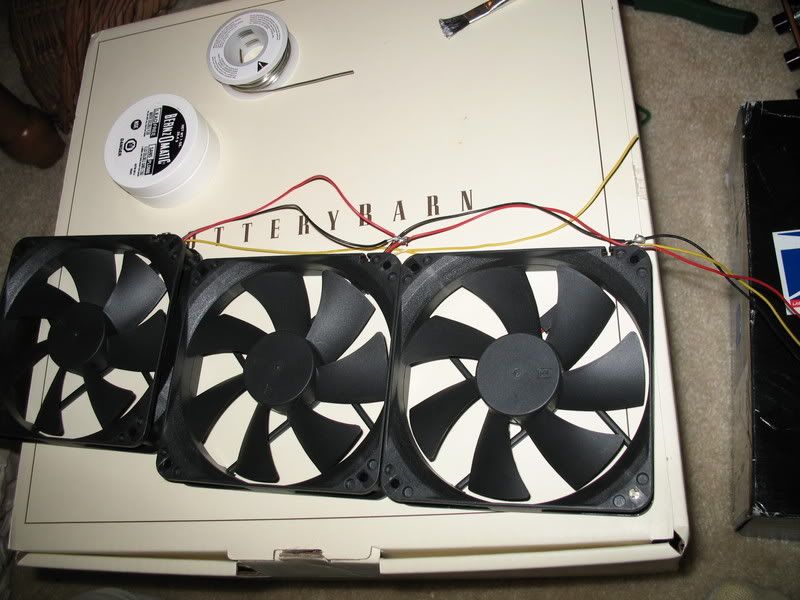
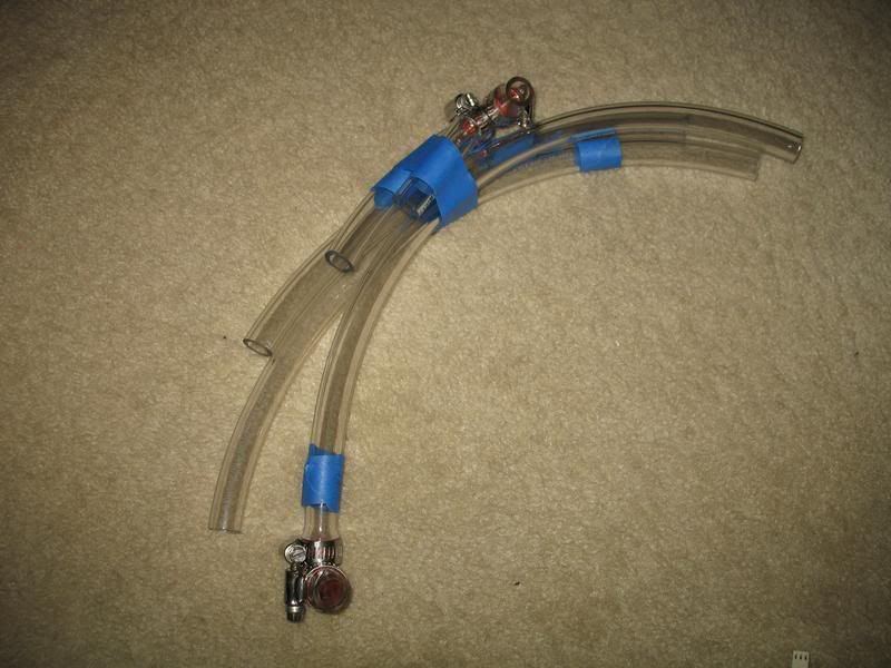
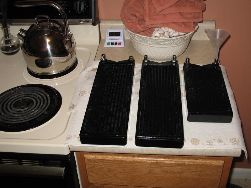
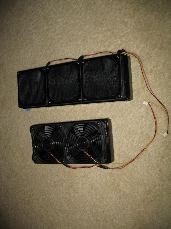
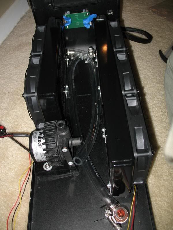
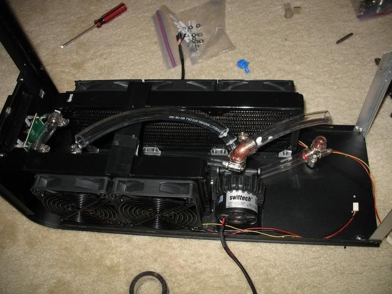
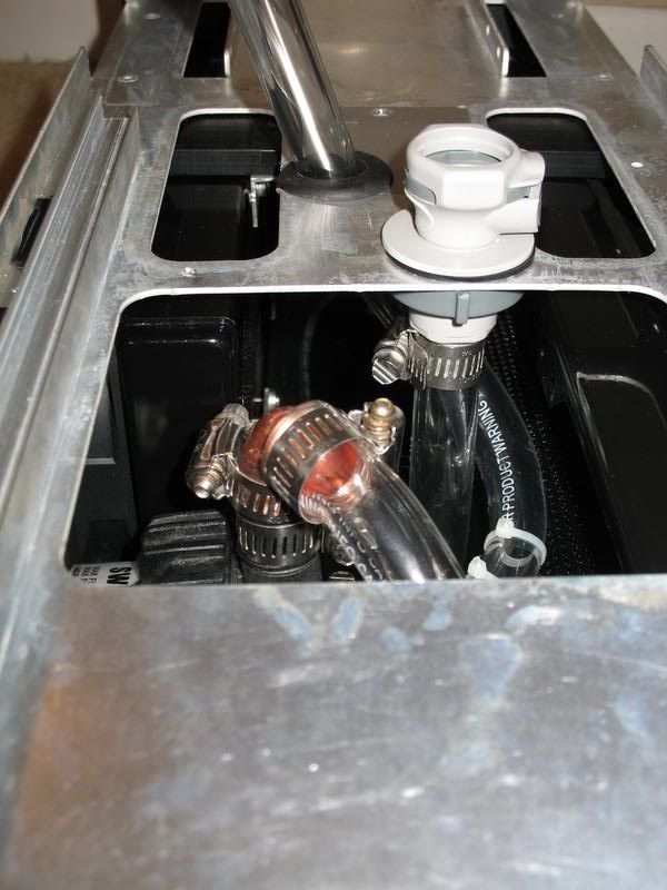
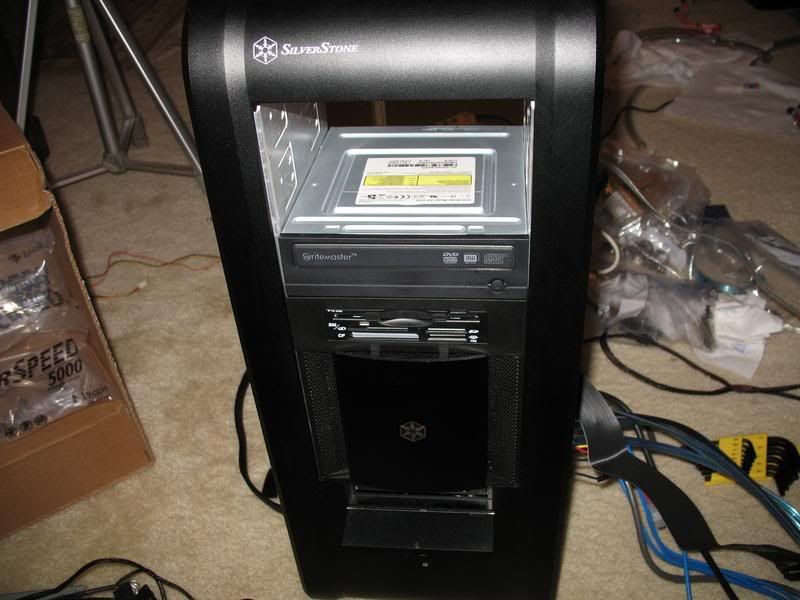
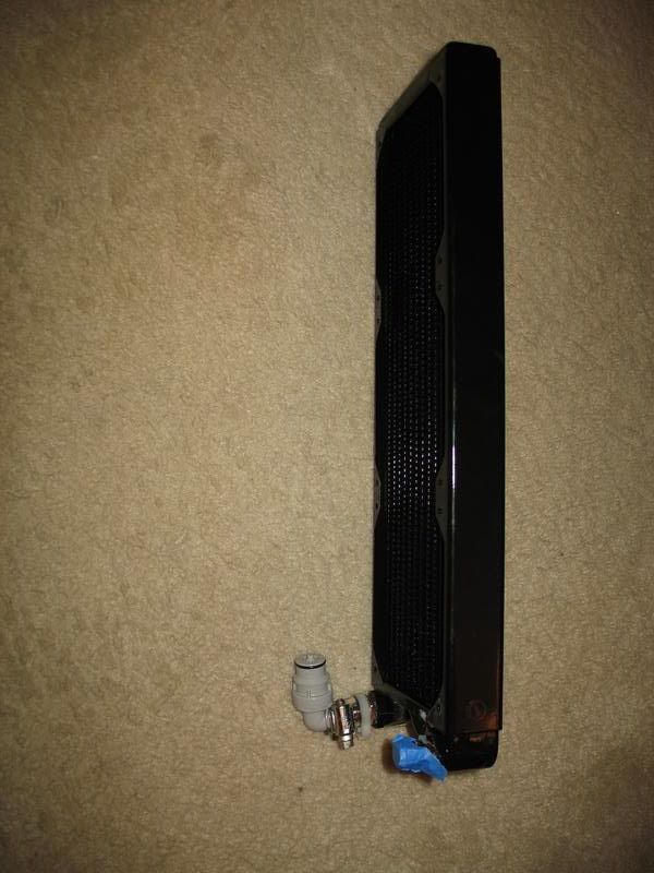
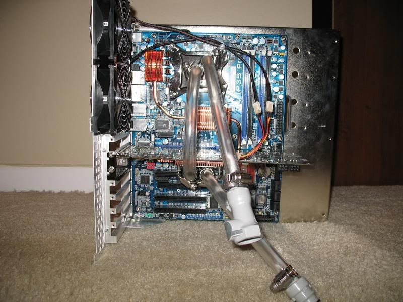
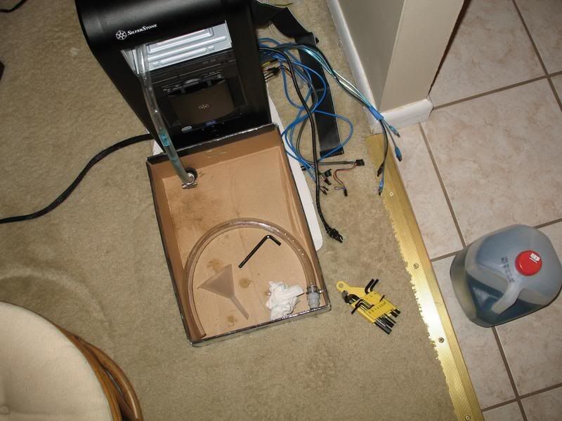
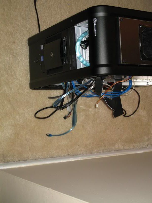
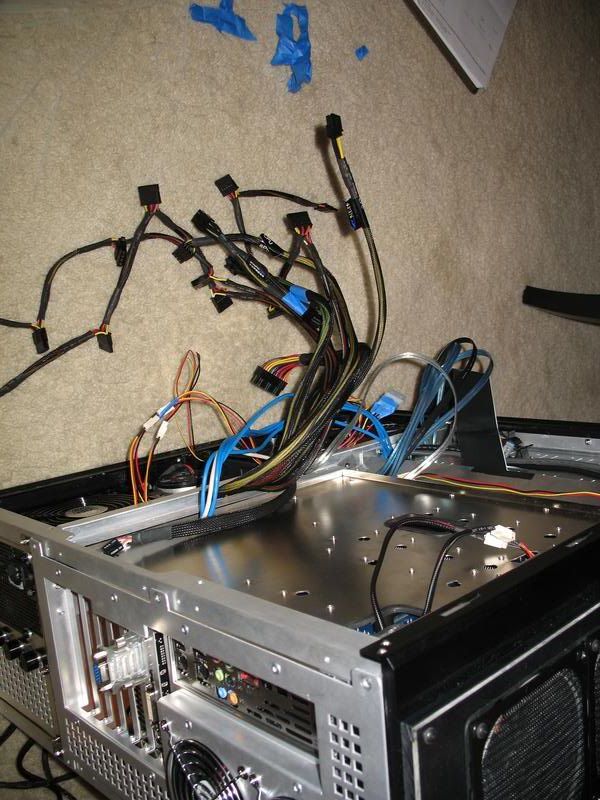
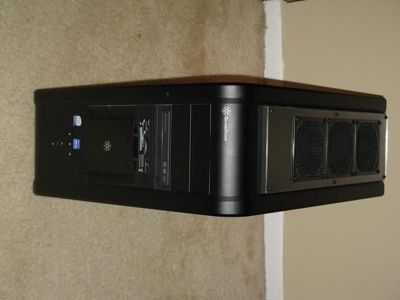
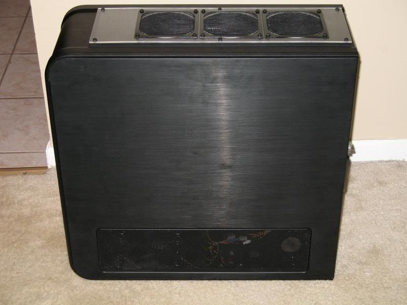
The top radiator assembly went together pretty easily.
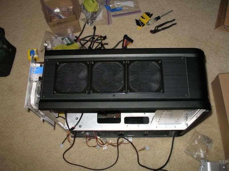
And looks pretty nice and clean, IMHO.
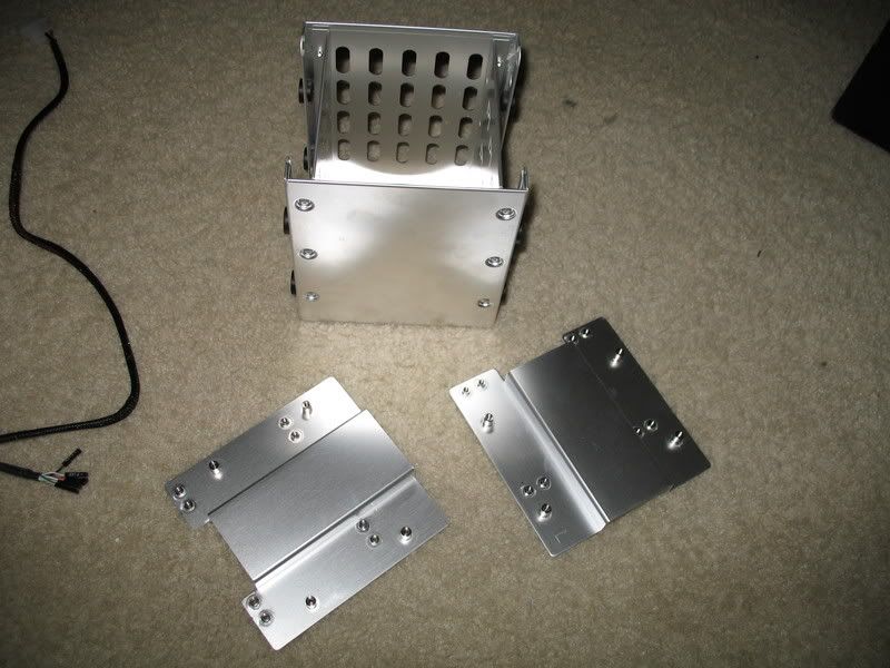
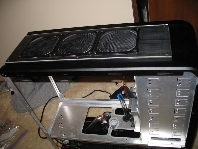
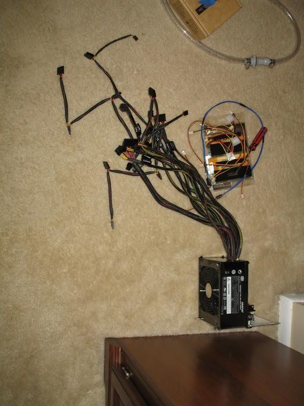
More assembly:

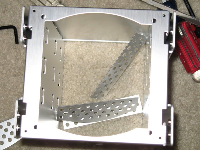
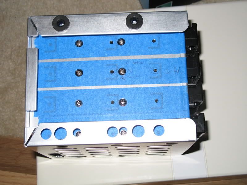
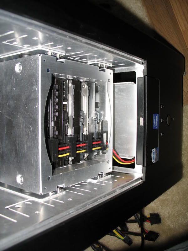
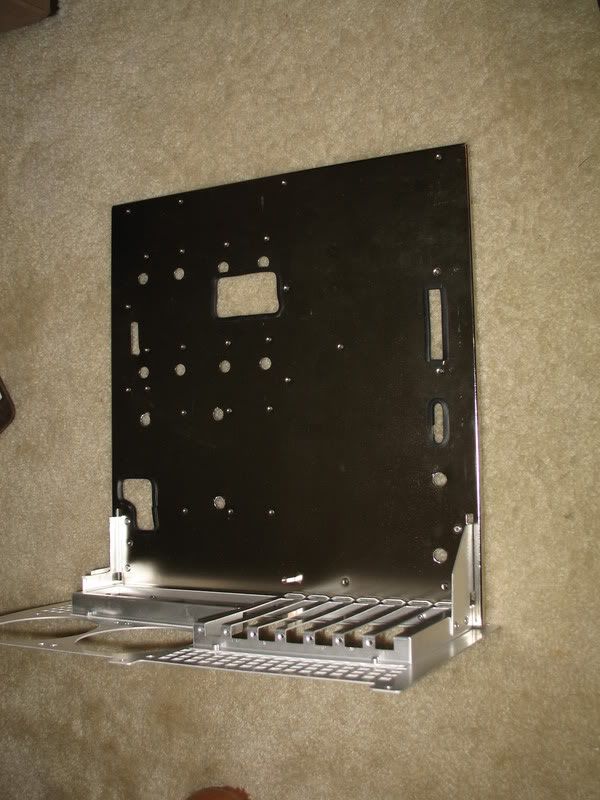
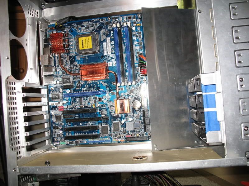
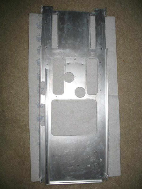
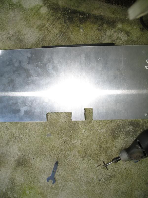
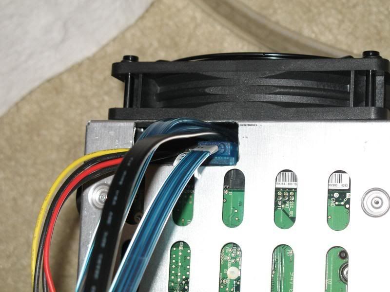
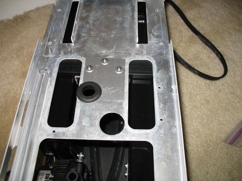
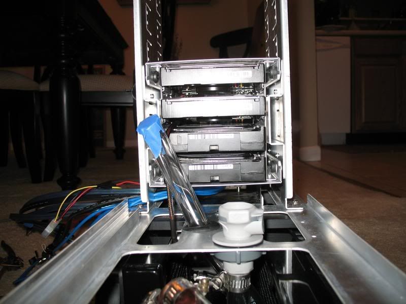
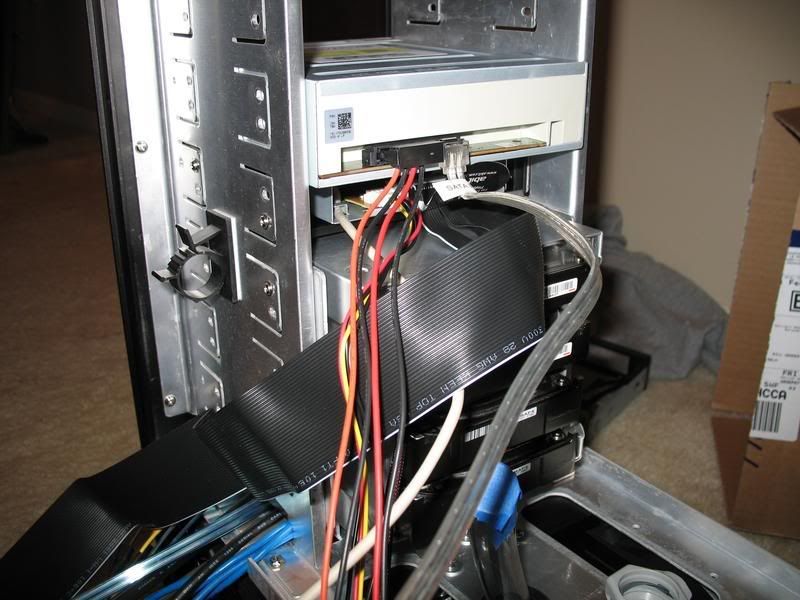
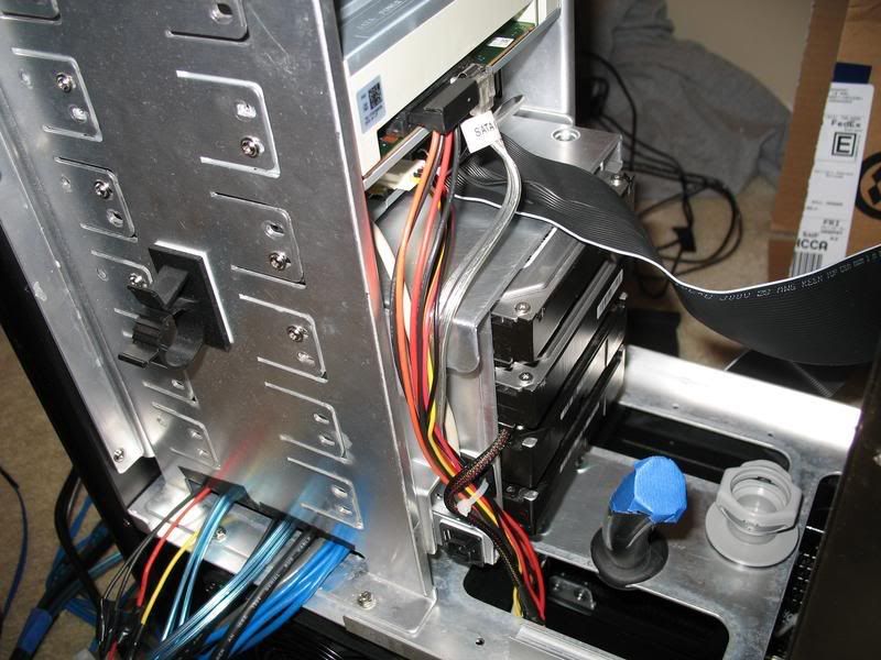
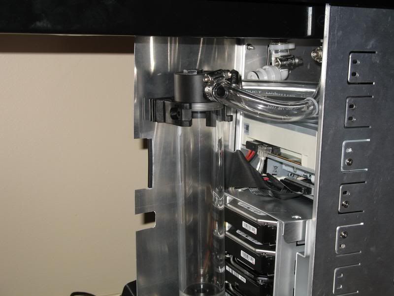
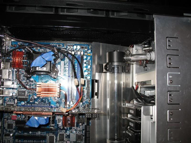
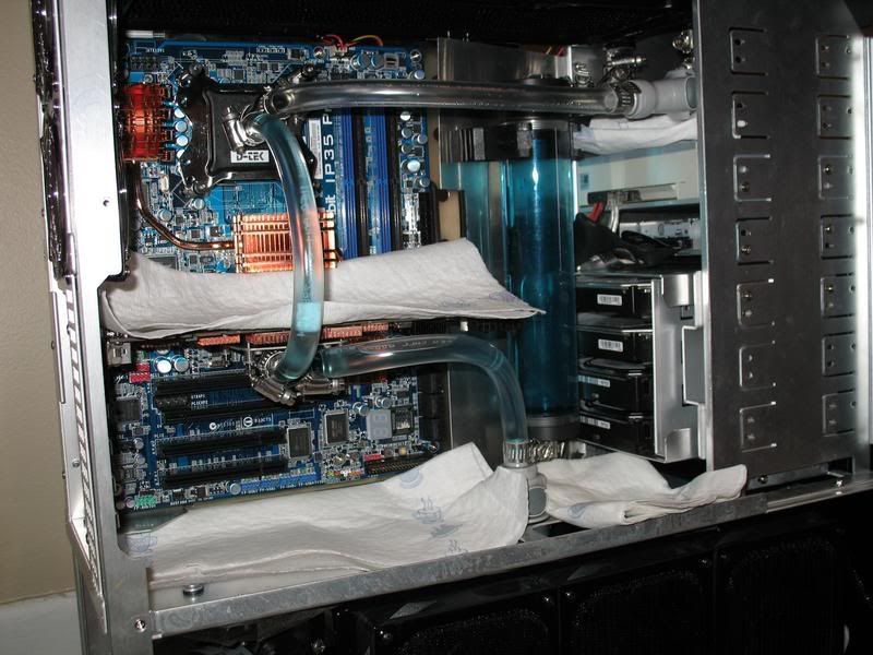
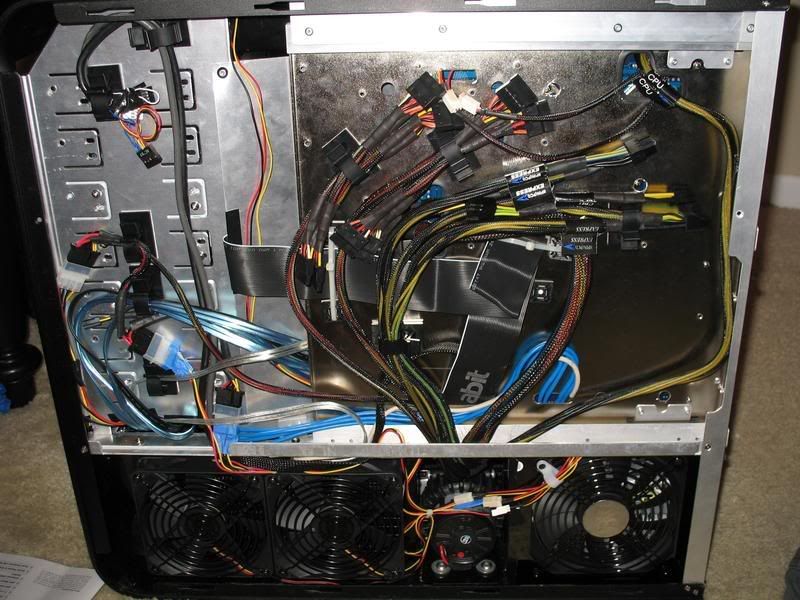
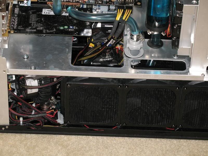
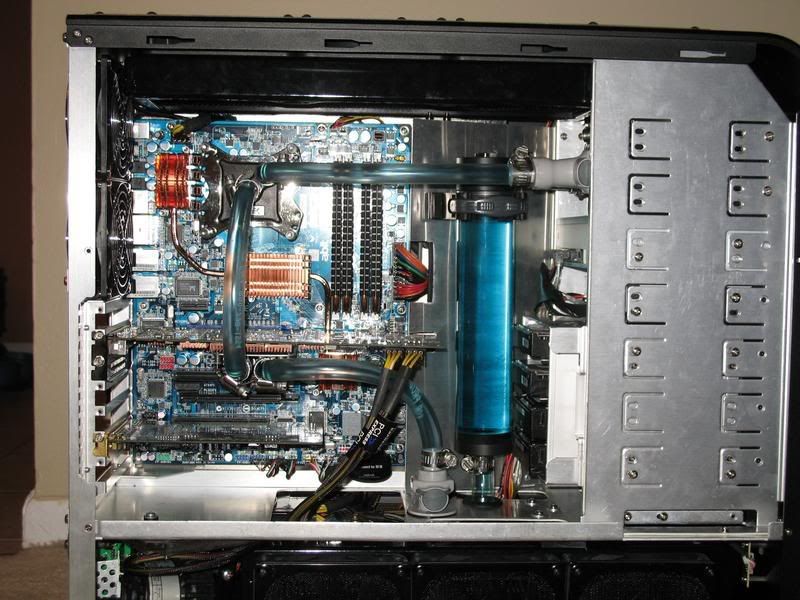
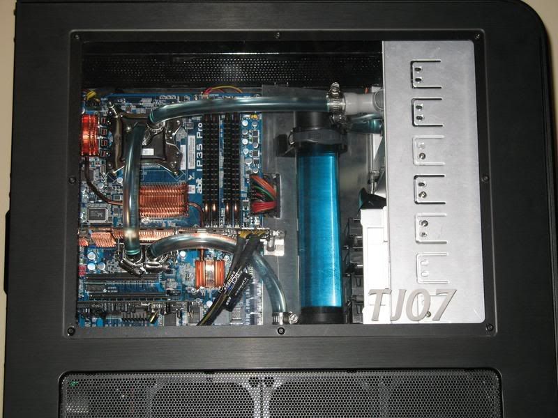
Here I've added the HDD rack and the aluminum panel I made. I mounted one of the HDDs in reverse to get an idea of what I'd have to deal with in order to completely hide the cables.
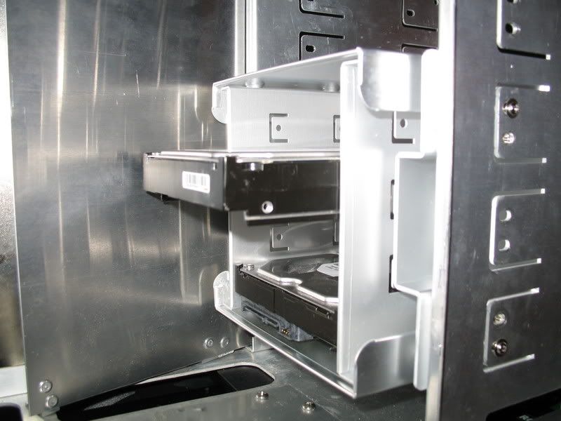
By drilling new holes, I can move that HDD in ~1.375" and still have room for the cables in the front. As of now I'm planning to do this on Saturday.
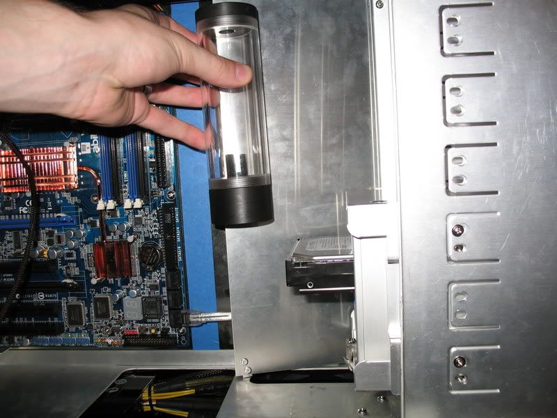
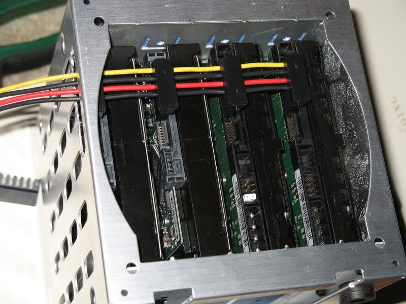
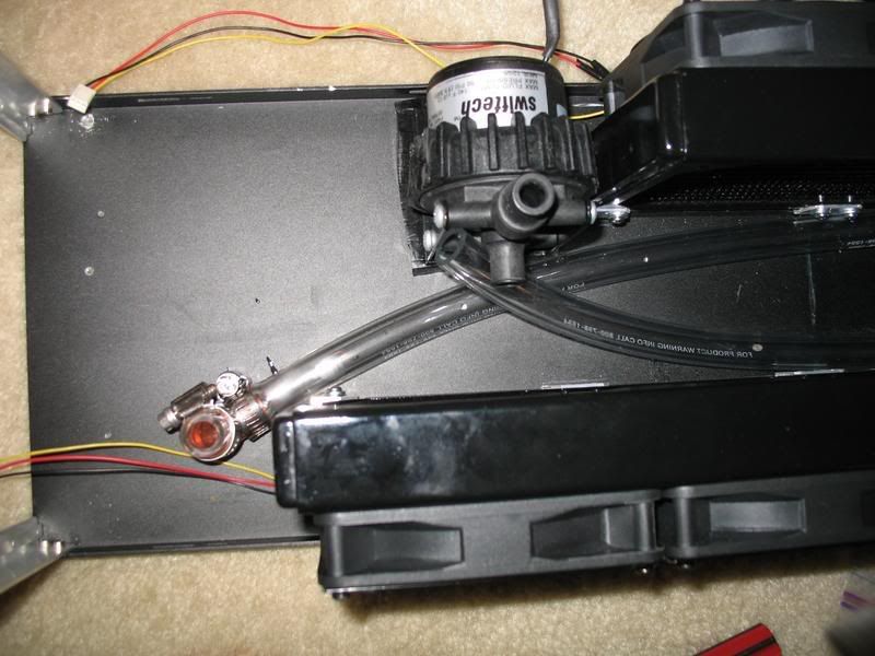
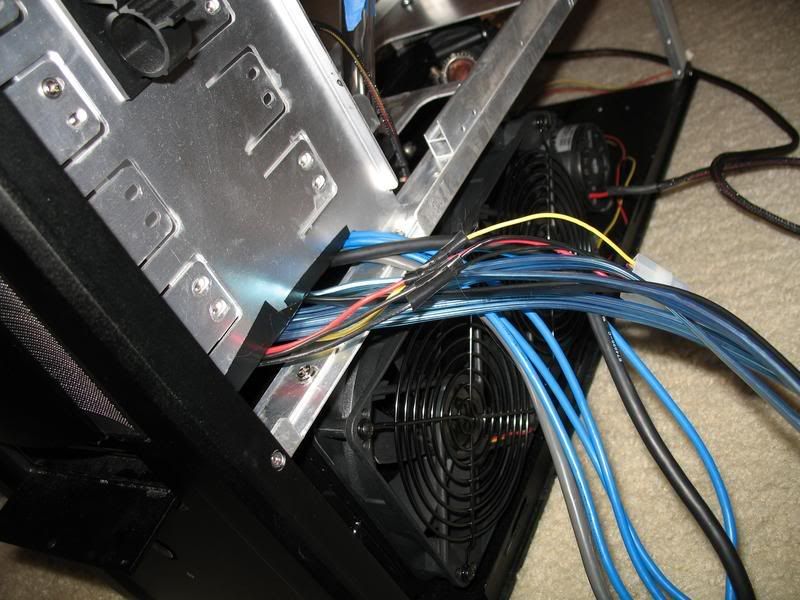
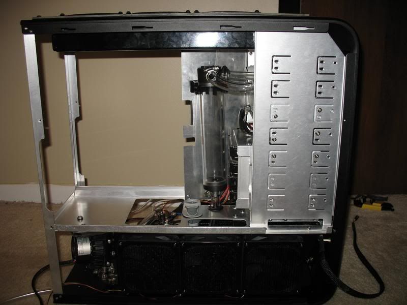
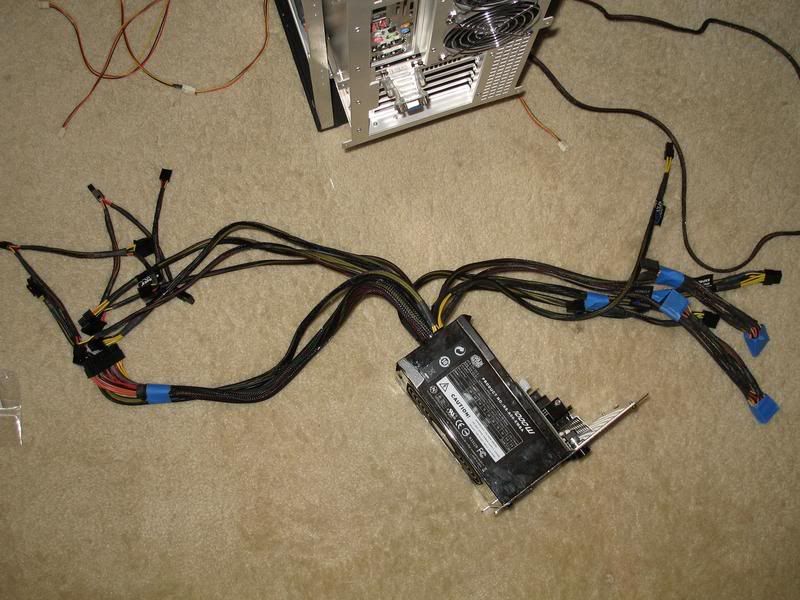
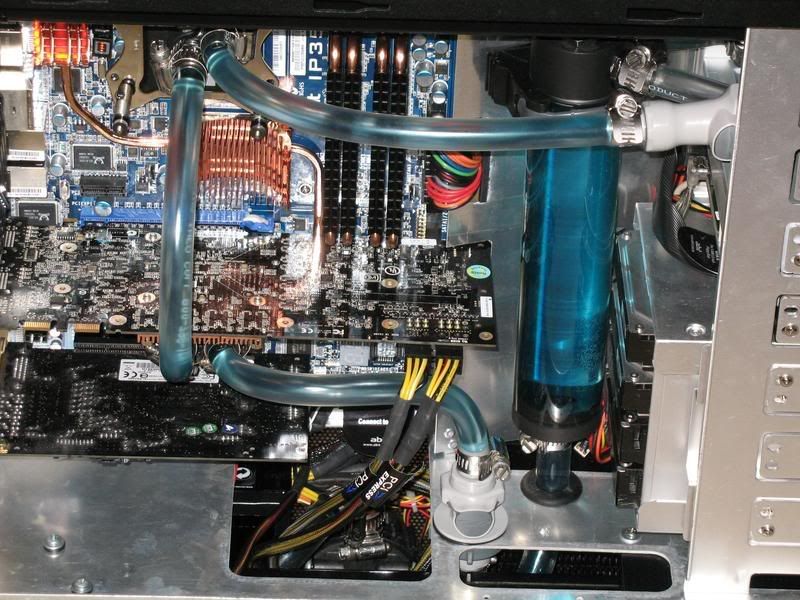
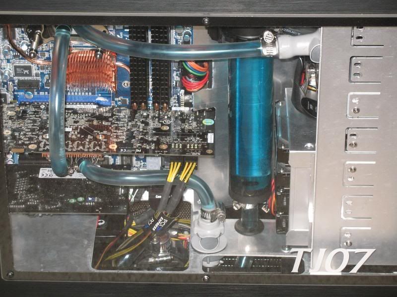
And here you can see one of the SATA cables plugged in and the general reservoir location. One picture that I'm kicking myself for not taking is before I added the top radiator assembly (which currently prevents the mobo tray from sliding all the way in), the edge of the motherboard (and that SATA cable) is completely hidden by the aluminum sheet. It looked awesome. However the main power cable is going to cause some serious problems because it won't bend hard enough. If they make 90 degree adapters for 24pin power cables, I need to find one.
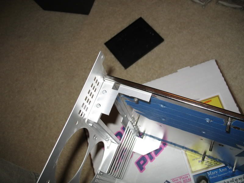
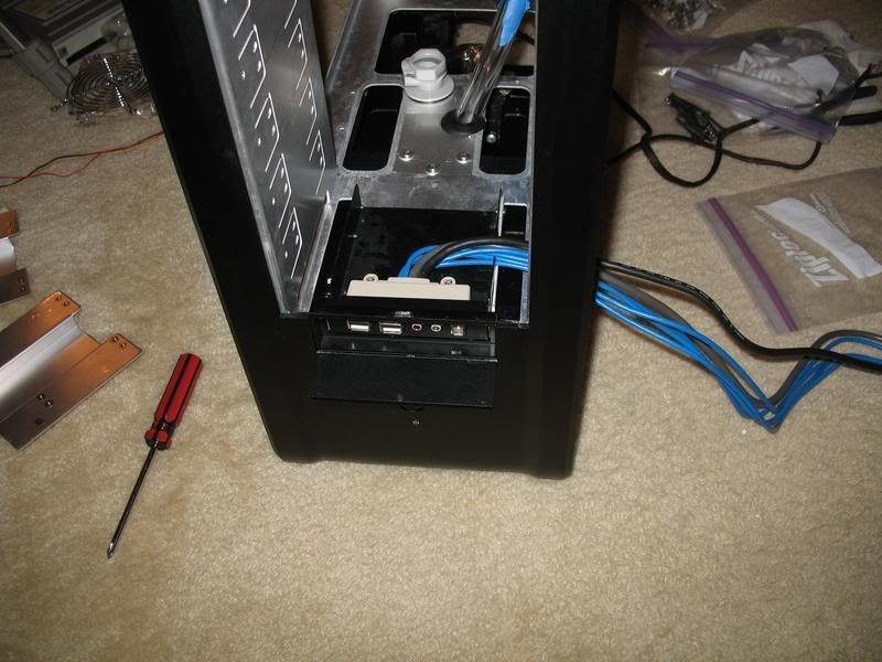
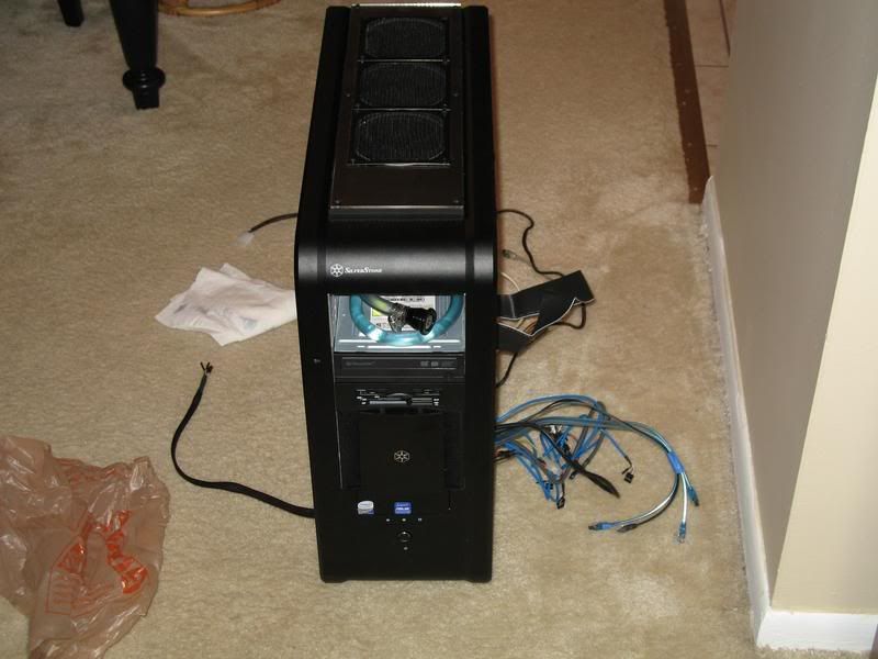
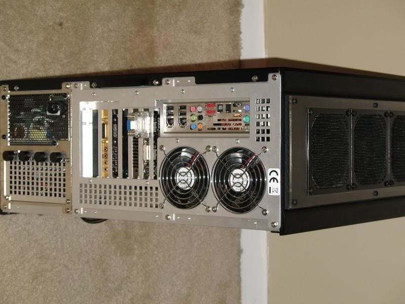
I also need to do some cutting on the motherboard tray for cabling, and the top rear bracket needs to be cut.

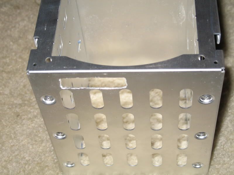
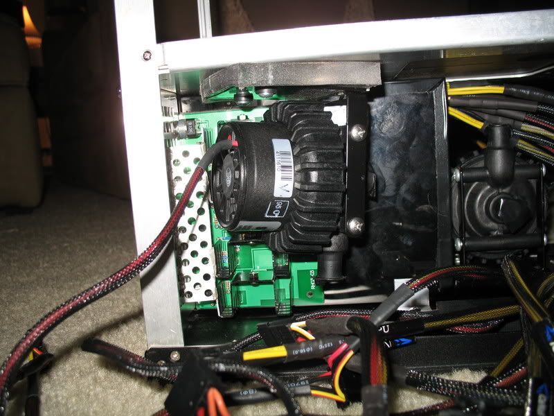
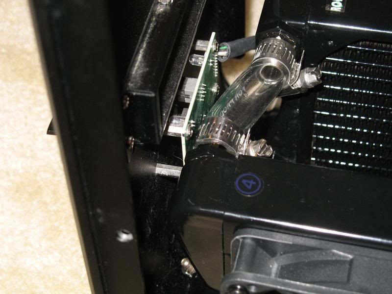
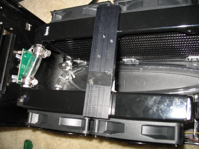
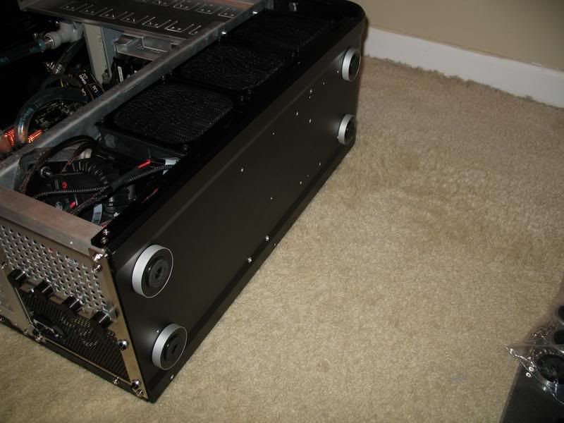
Since I switched to a 6mm spacer plate from the 3mm one, I was thinking that this bracket (taped) might clear the radiator - close, but no cigar. Yeah, I'll try to clean up that nylon edge, too.
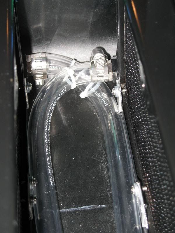
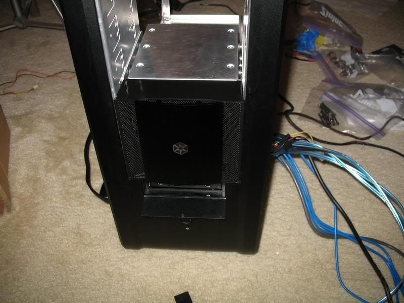
That's pretty much where I'm at. Everything is going to fit, although the tubes are going to be a royal PITA to install. There's a bunch of small things that need to be done, but the end is in sight.
At this point the lower part of the case is pretty well taped out. Here you can see that assembly is completely feasible.
So I figured I'd try to assemble the top portion and find out what still needs to be done up there. It was also an excuse to open up some hardware.
The top radiator assembly went together pretty easily.
And looks pretty nice and clean, IMHO.
More assembly:
Here I've added the HDD rack and the aluminum panel I made. I mounted one of the HDDs in reverse to get an idea of what I'd have to deal with in order to completely hide the cables.
By drilling new holes, I can move that HDD in ~1.375" and still have room for the cables in the front. As of now I'm planning to do this on Saturday.
And here you can see one of the SATA cables plugged in and the general reservoir location. One picture that I'm kicking myself for not taking is before I added the top radiator assembly (which currently prevents the mobo tray from sliding all the way in), the edge of the motherboard (and that SATA cable) is completely hidden by the aluminum sheet. It looked awesome.
However the main power cable is going to cause some serious problems because it won't bend hard enough. If they make 90 degree adapters for 24pin power cables, I need to find one.I also need to do some cutting on the motherboard tray for cabling, and the top rear bracket needs to be cut.
Since I switched to a 6mm spacer plate from the 3mm one, I was thinking that this bracket (taped) might clear the radiator - close, but no cigar. Yeah, I'll try to clean up that nylon edge, too.
That's pretty much where I'm at. Everything is going to fit, although the tubes are going to be a royal PITA to install. There's a bunch of small things that need to be done, but the end is in sight.
Last edited: