Taking my TJ07 to the watcooling extreme

NicePants42

Partition Master
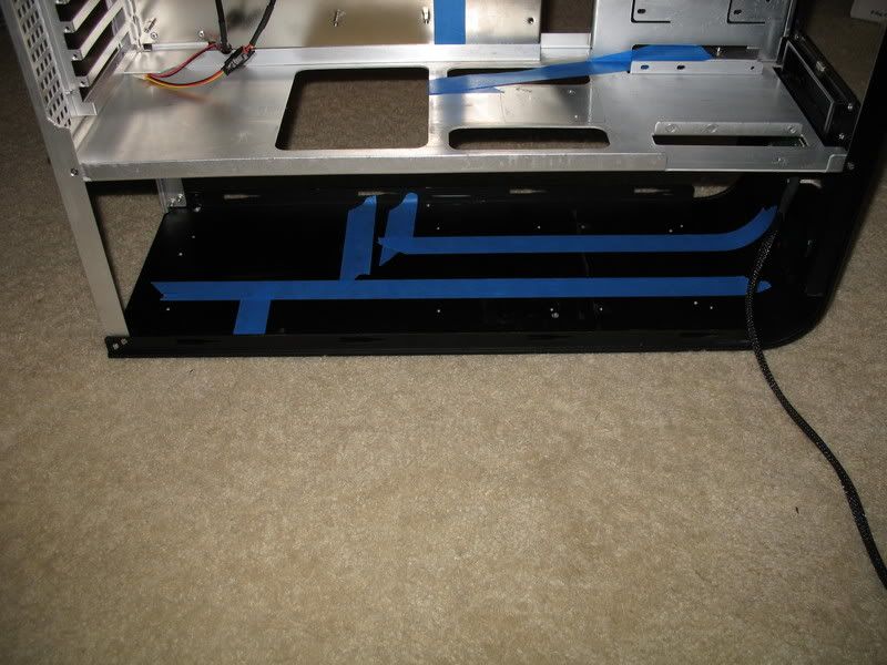
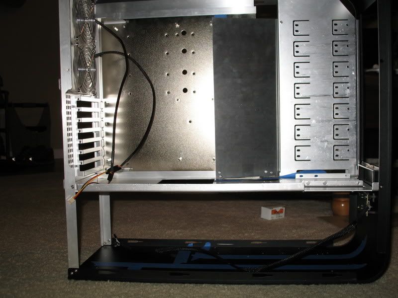
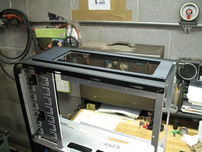
Last January I was lucky enough to get my hands on a second-hand TJ07 and some water cooling gear. The first owner had setup up a dual loop system, which I kept with only aesthetic changes until yesterday, when I started work on this project.

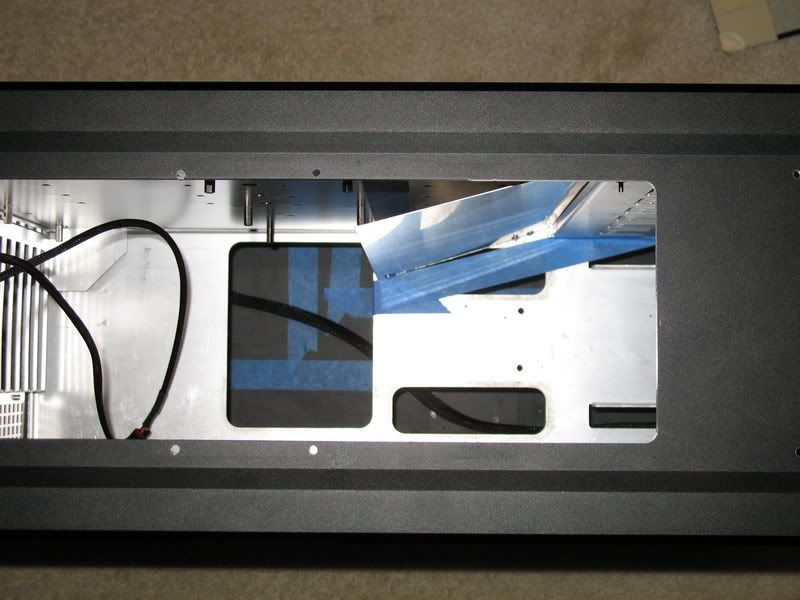
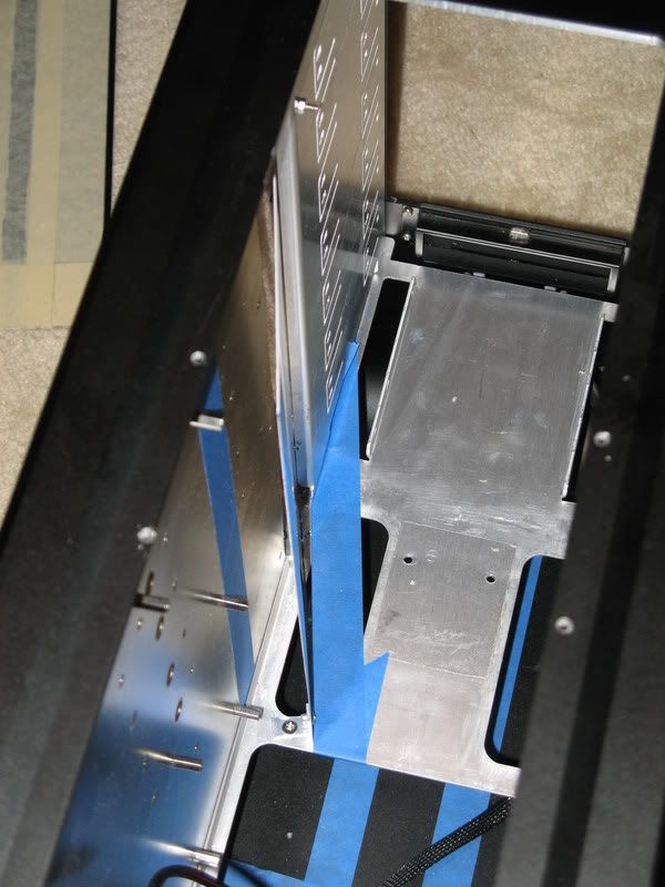
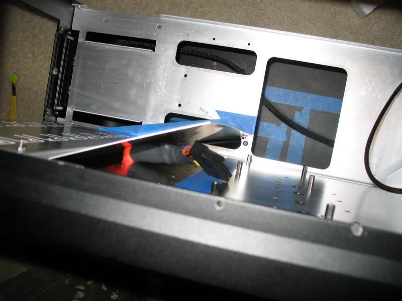
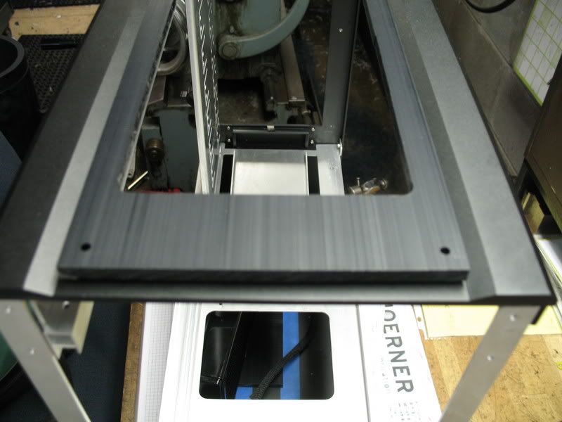
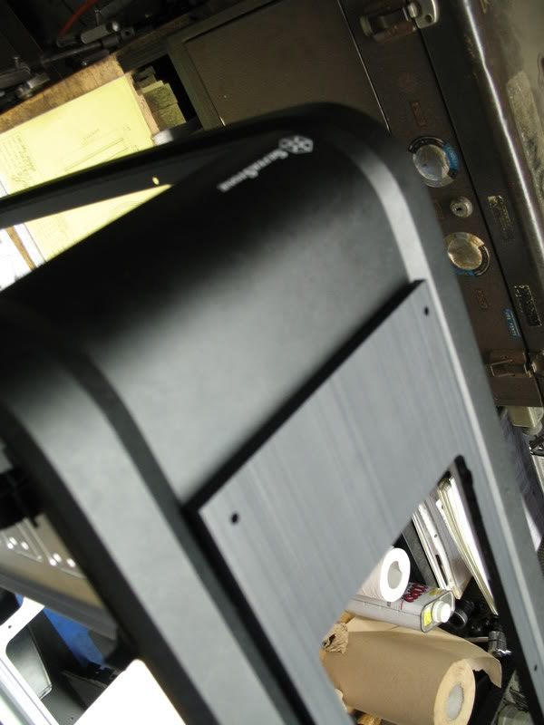
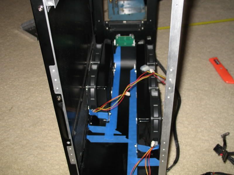
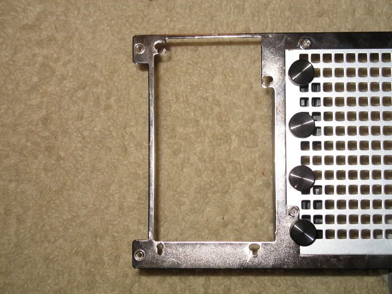
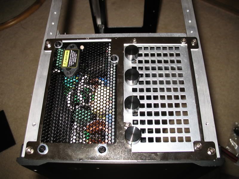
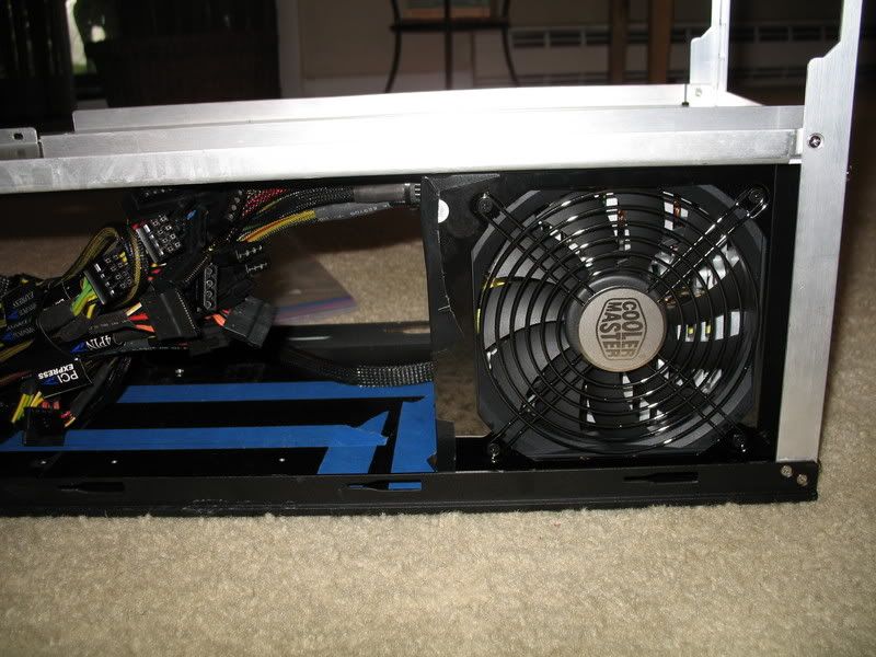
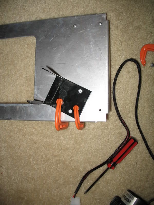
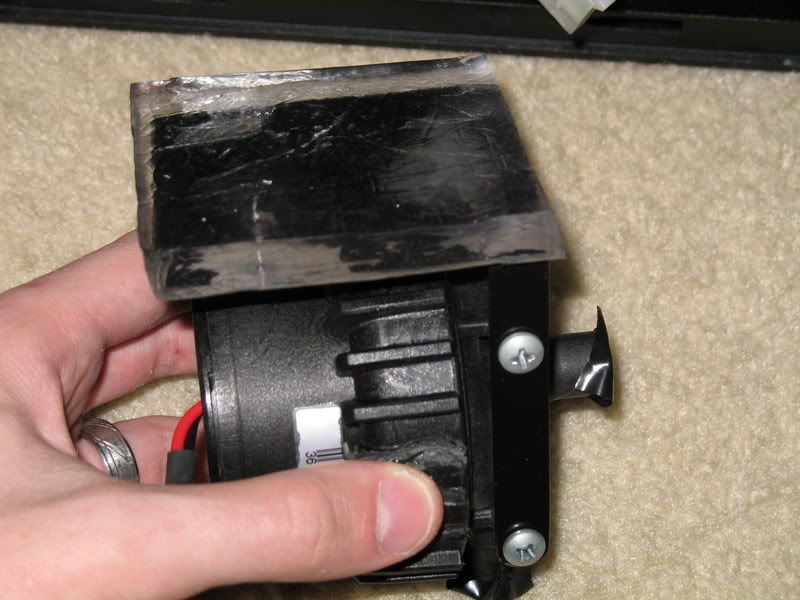
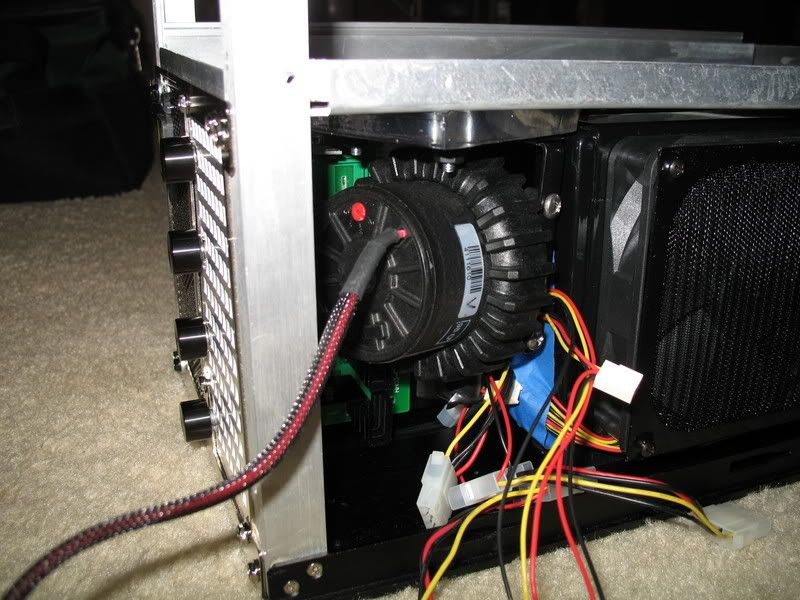
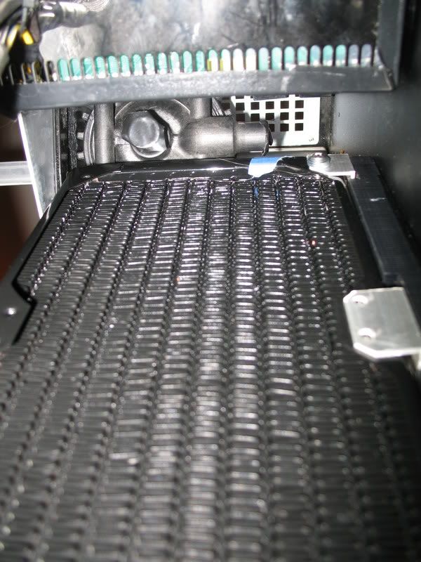
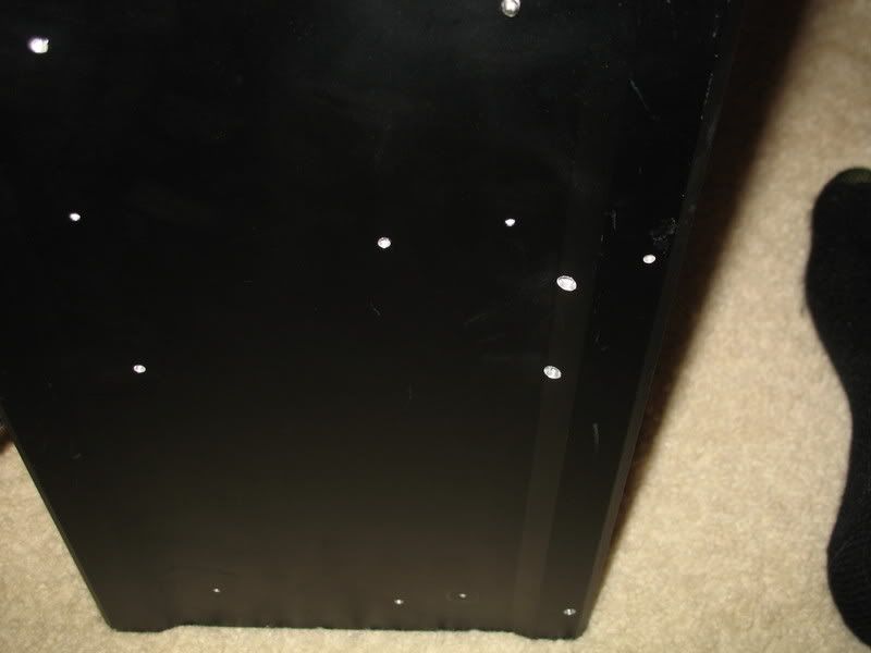
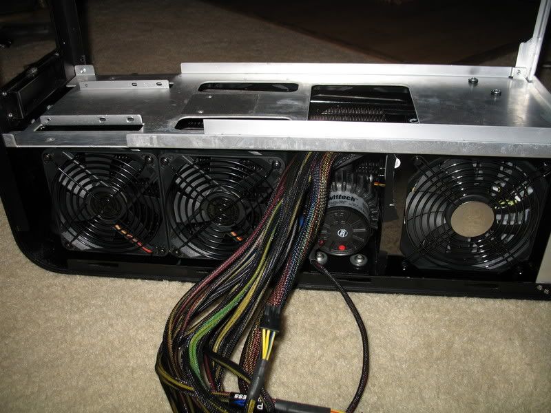
First I'll show you what I'm starting from.
IMG_0564.jpg

IMG_2066.jpg

IMG_2065.jpg

IMG_0560.jpg

IMG_0648.jpg

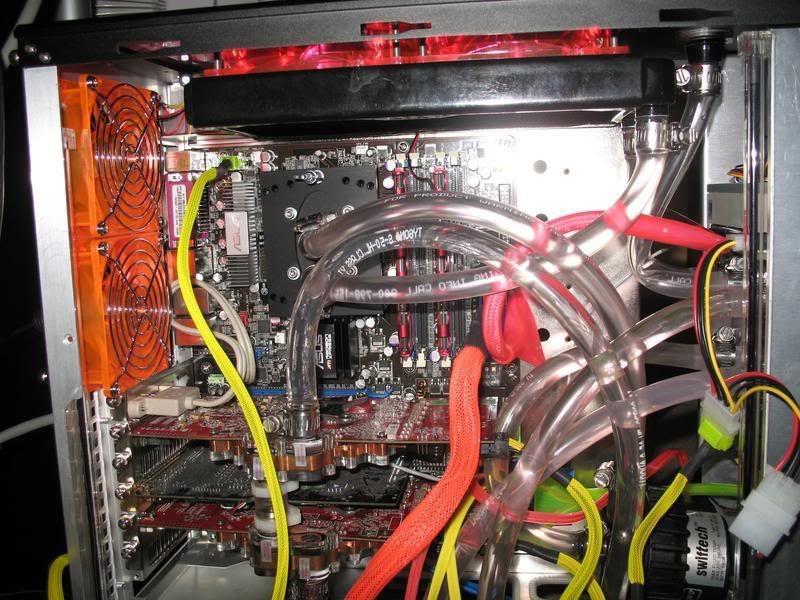
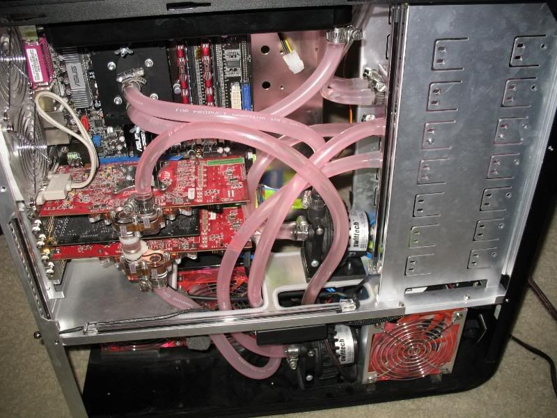
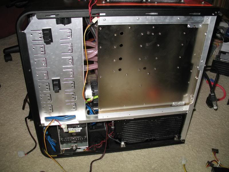
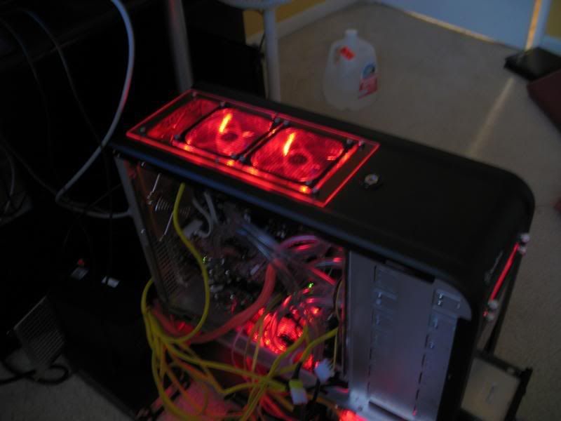
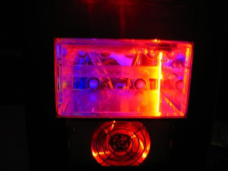
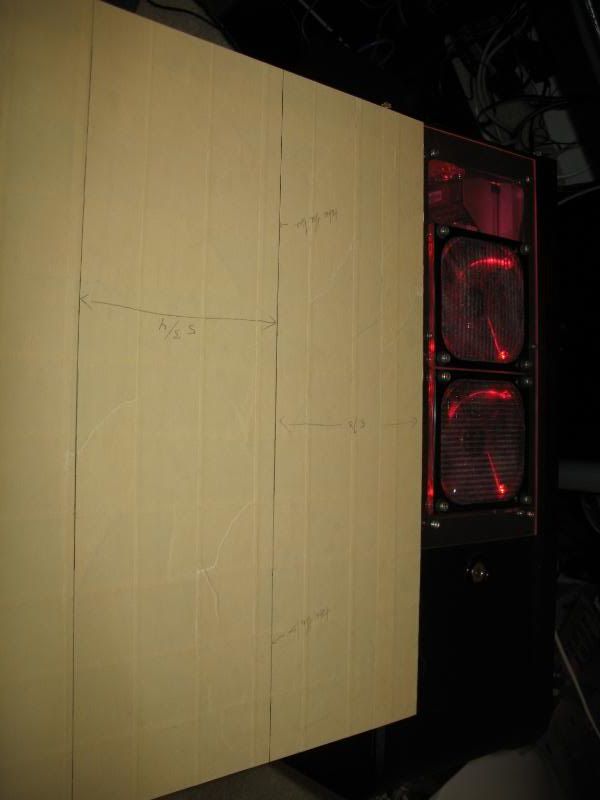
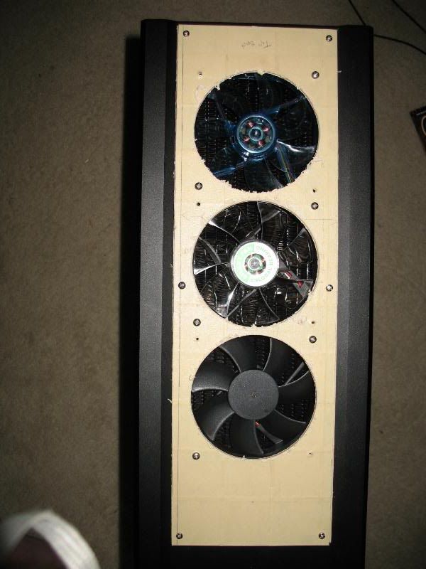
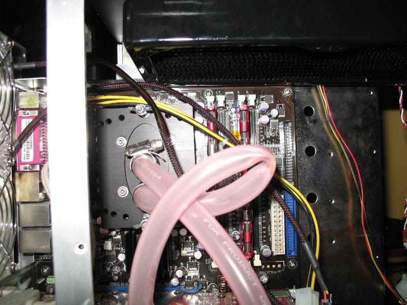
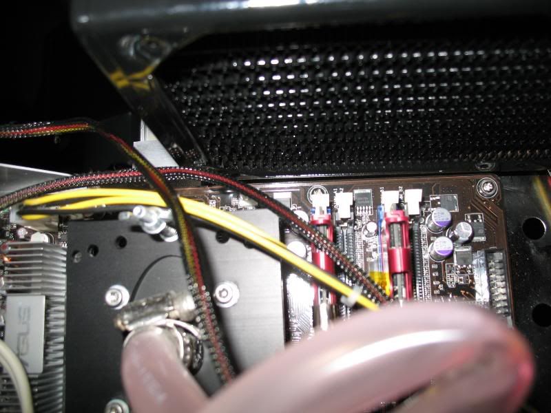
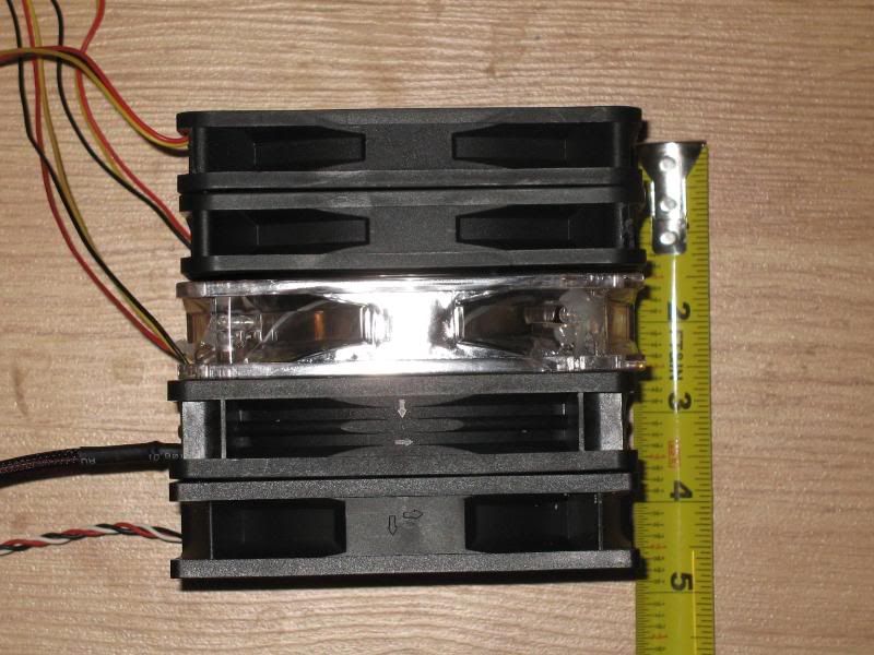
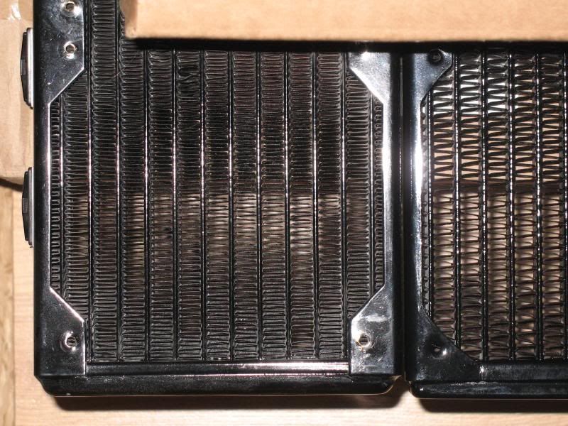
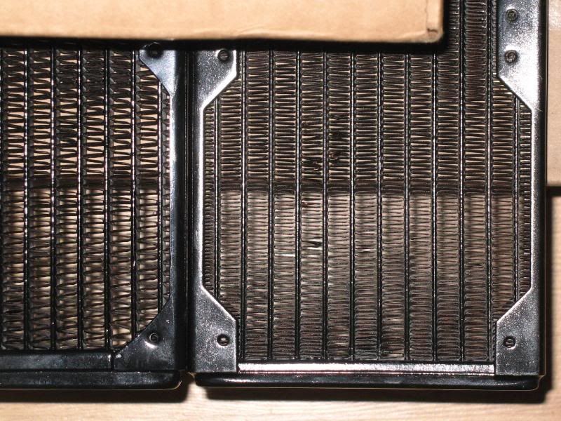
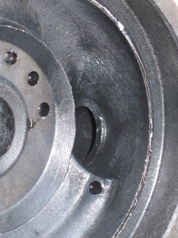
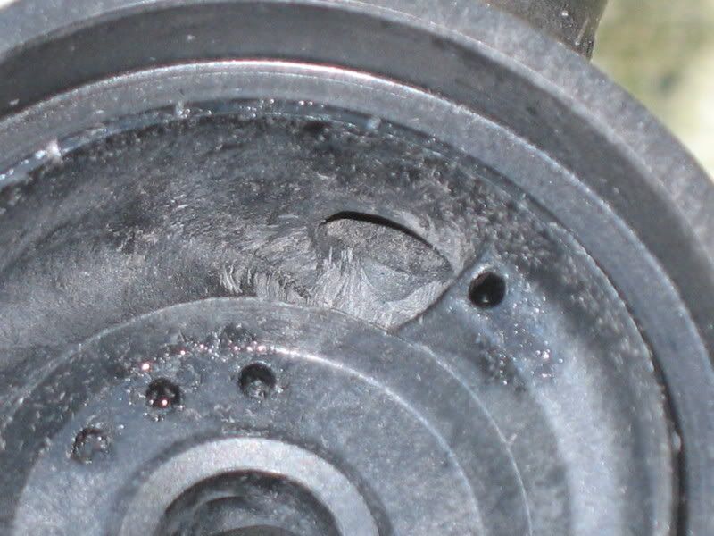
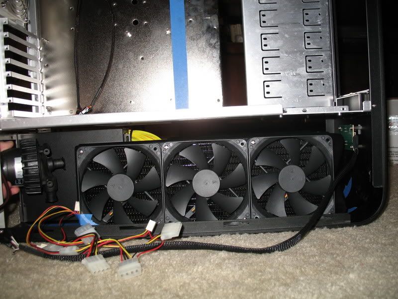
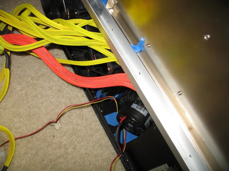
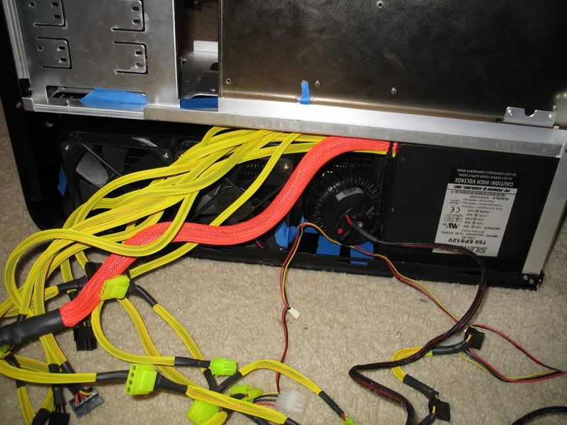
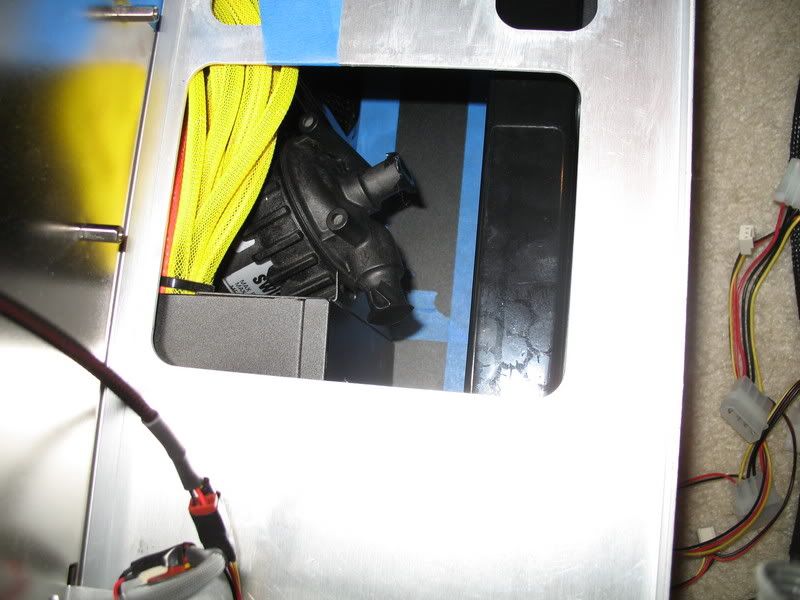
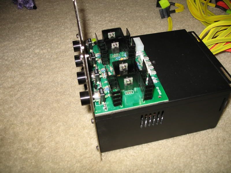
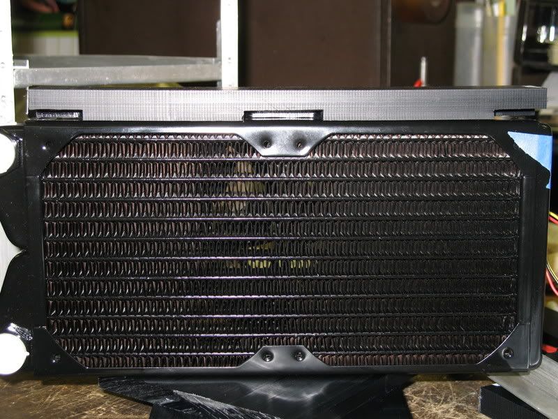
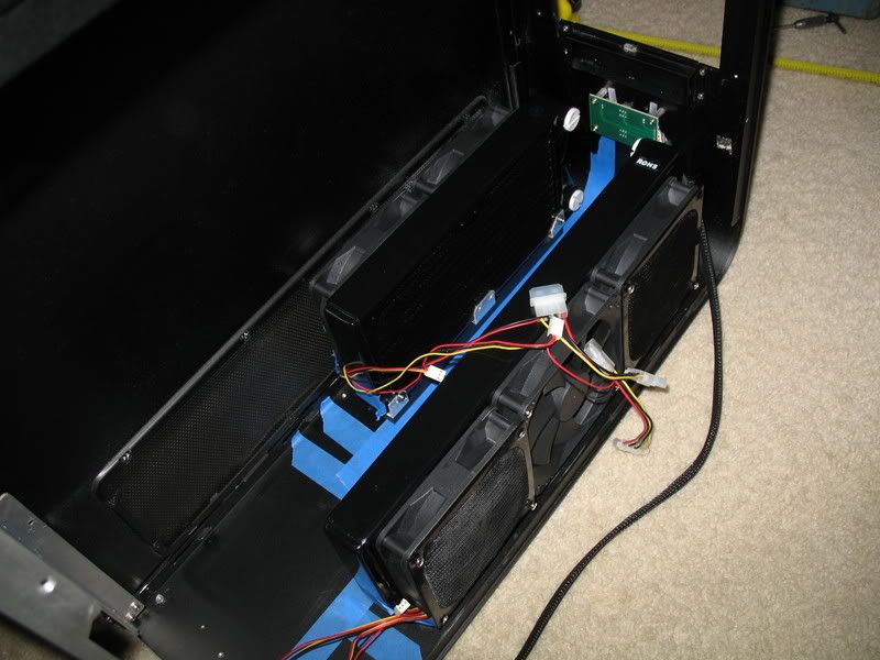
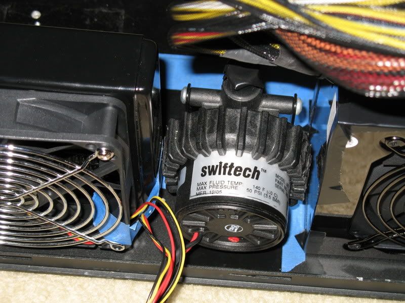
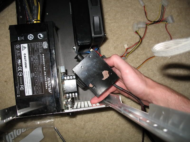
From these you can see that the loops share a common bay reservoir, and each loop is powered by an MCP655 pump. The CPU loop uses a BIP2 installed in the top of the case, while the GPU loop uses a BIX2 installed in the bottom. I was going for a back/red theme with some yellow highlights, so I used UV red plexi to help mount the BIP2.

IMG_0642.jpg

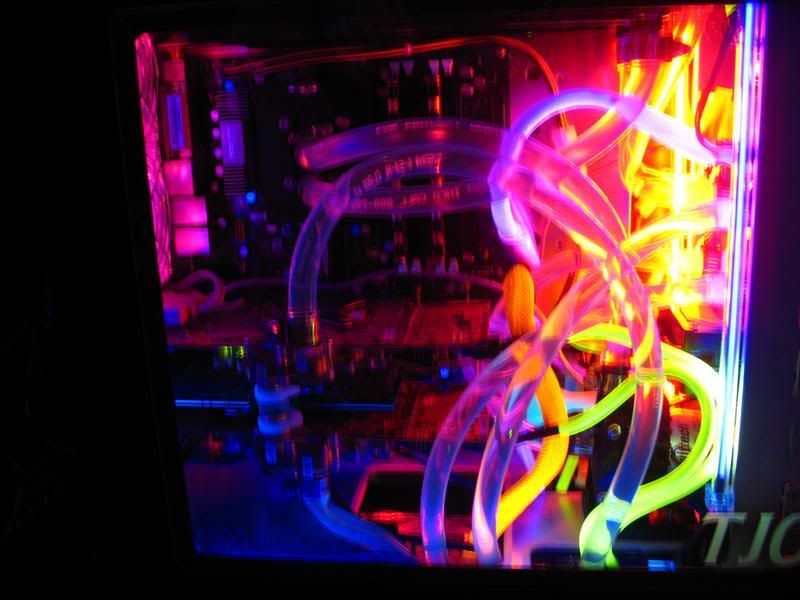
I have not been able to find a red UV coolant that's actually RED.

It's been said that the TJ07 is the best water cooling case on the market, and that it's perfect when too much is just right. With this project, I want to show how much I agree with these statements and create a tribute to overkill water cooling. I am hoping to be able to cram the following parts into this build, with everything mounted internally:

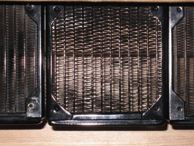
two Swiftech MCR320 radiators (one in top, one in base)
one Swiftech MCR220 radiator (in base)
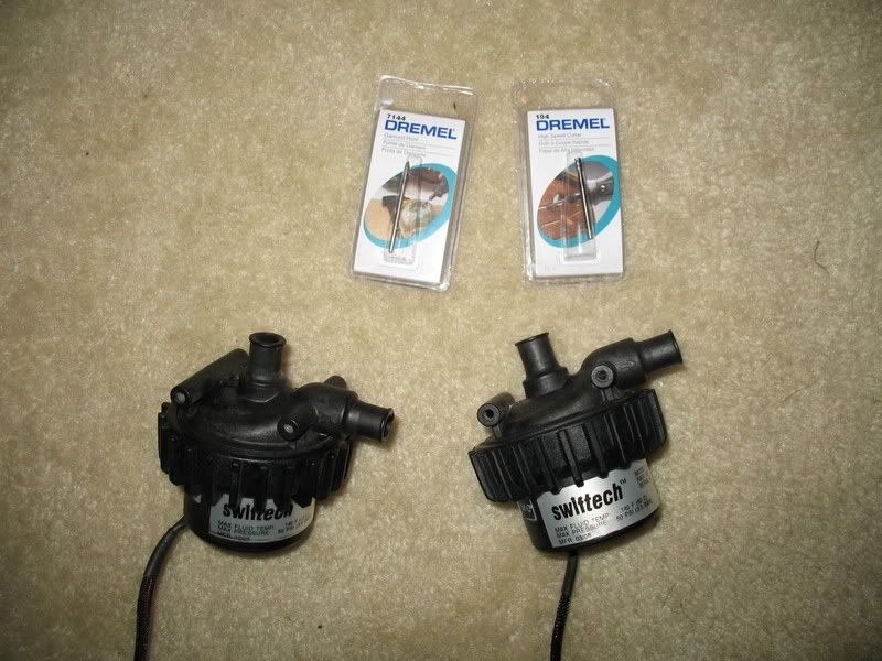
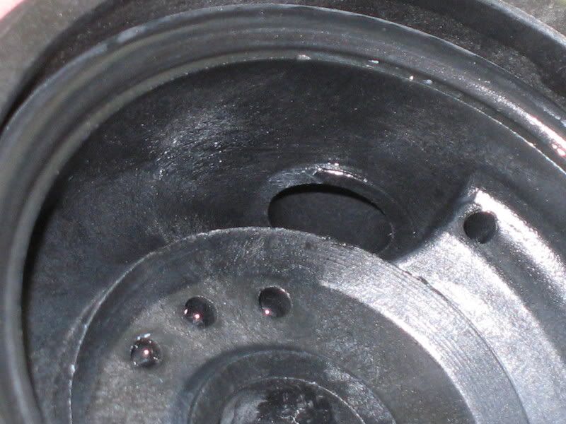
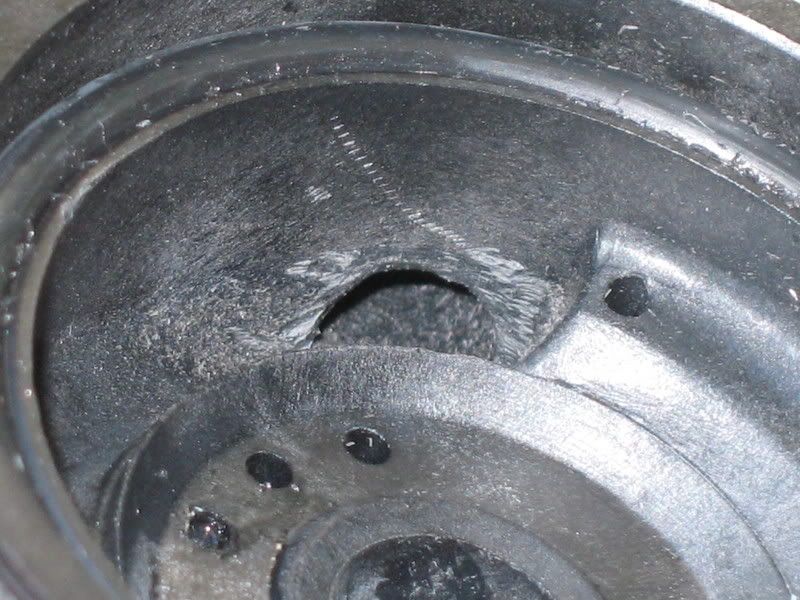
two Swiftech MCP655 pumps run in series (in base)
D-tek Fusion CPU Block
Swiftech MCW60 GPU block (possibly two)
Swiftech MCW30 Northbridge block (or stock ASUS Blitz Formula)
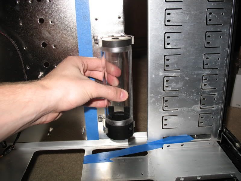
EK Multi-option res 150

I also plan to use two quick-disconnect fittings (from Colder) so that I can easily remove the motherboard tray without draining the loop. We'll have to see how the space issue works out.

There are a lot of fantastic TJ07 project logs out there, and I will be borrowing heavily from them for most of this project. Two projects in particular that I recommend are Ladderman's and AndyM's.

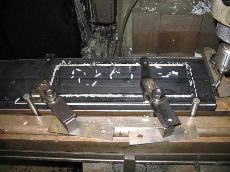
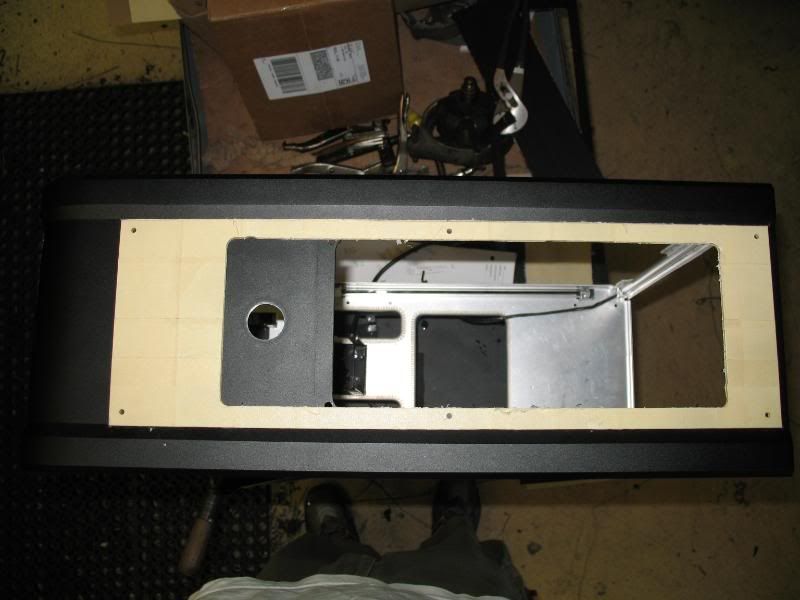
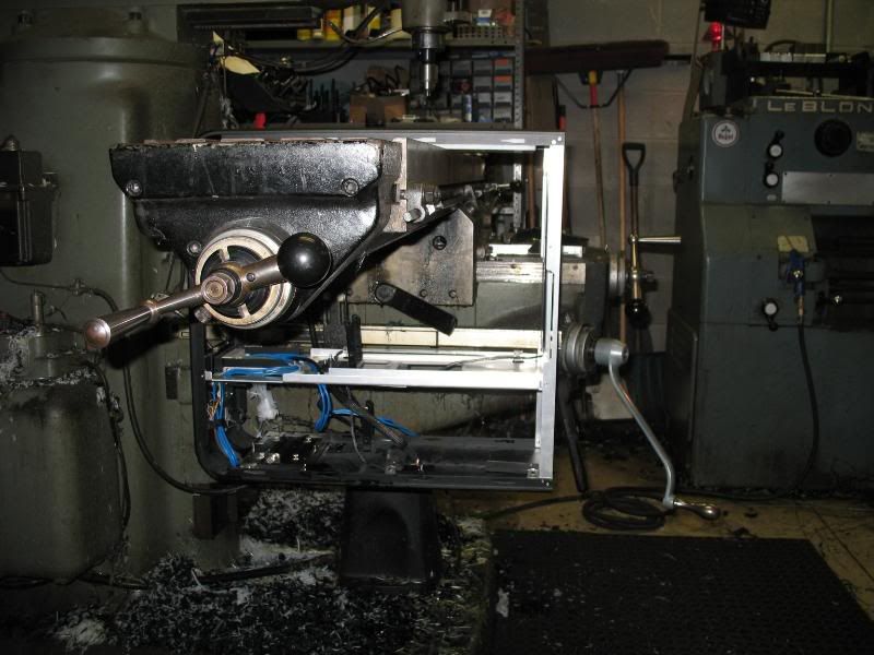
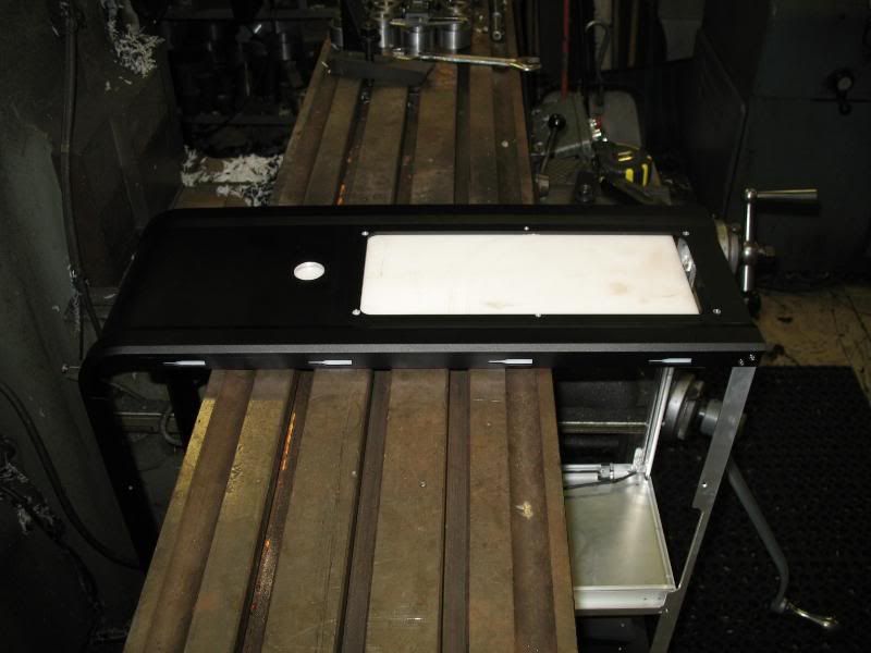
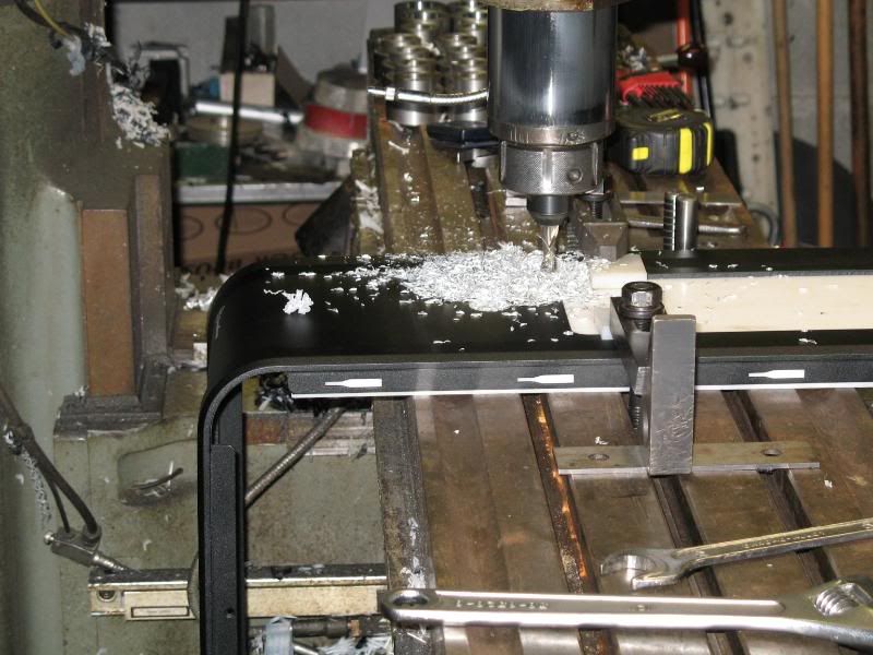
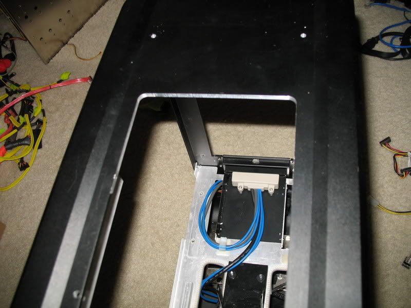
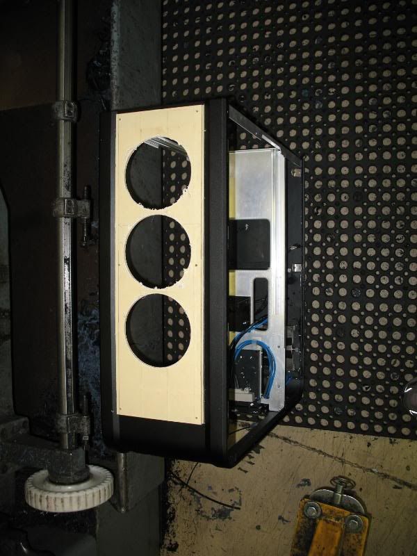
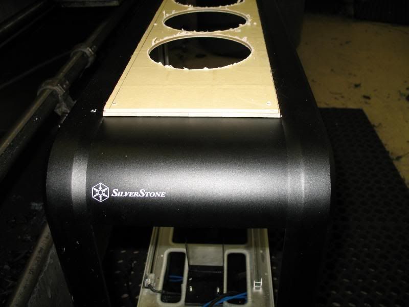
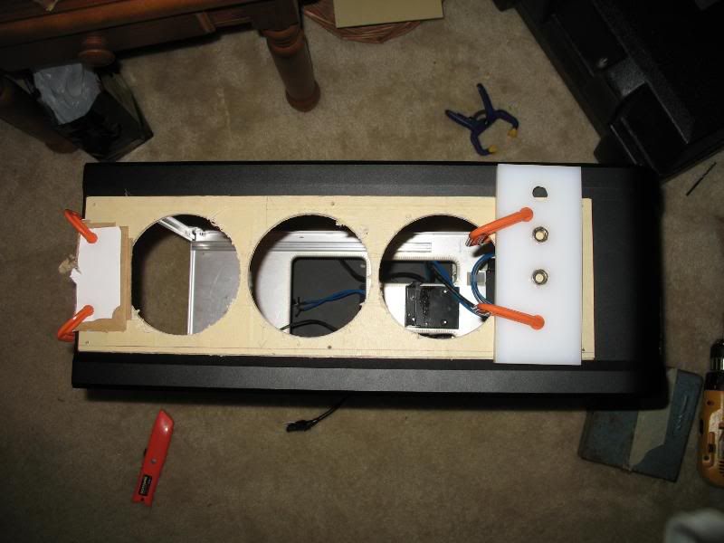
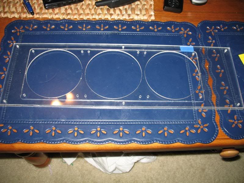
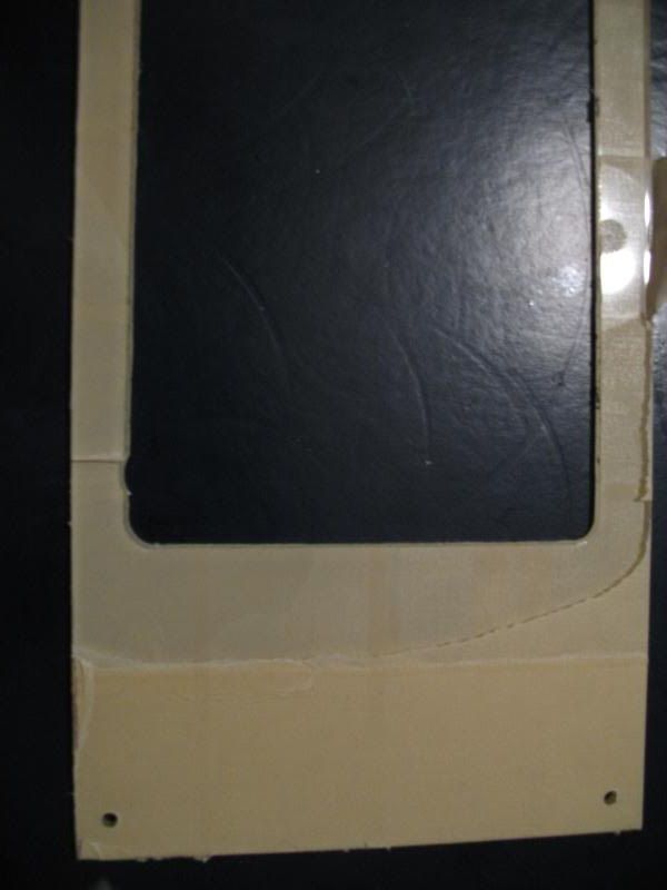
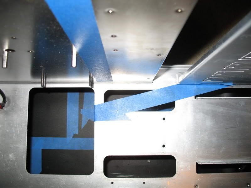
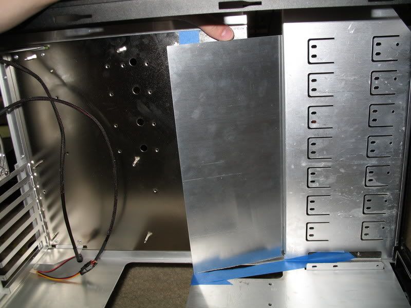
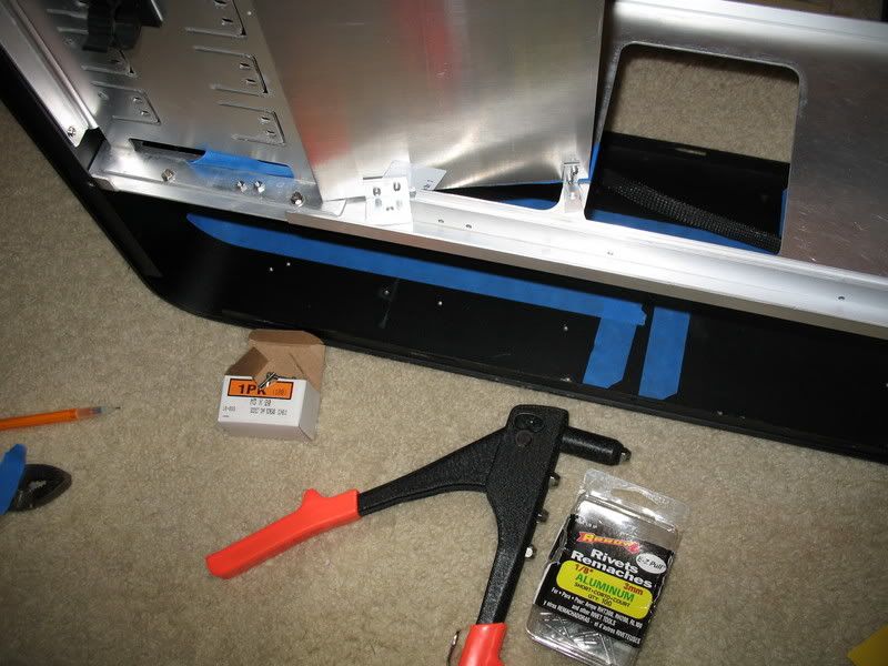
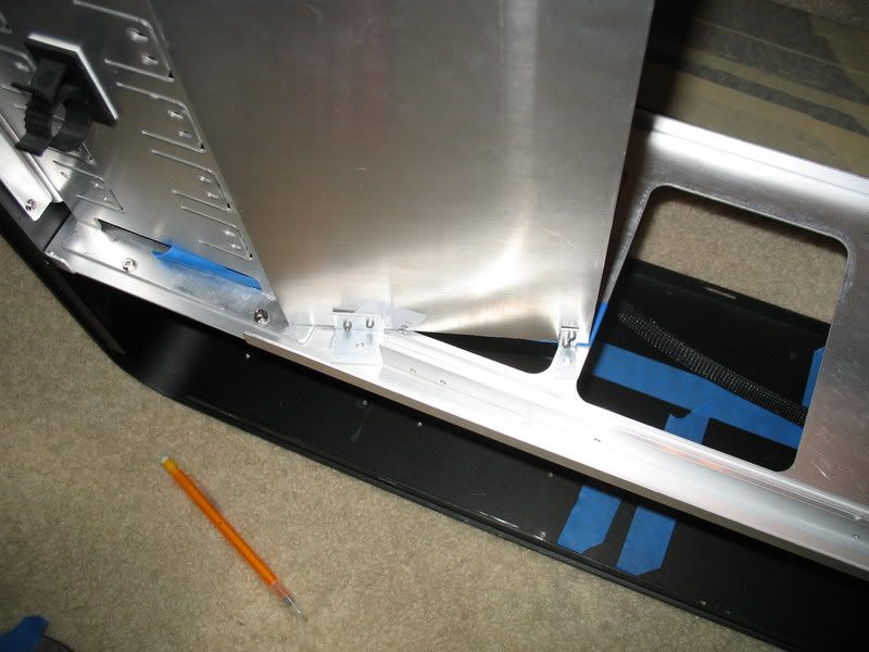
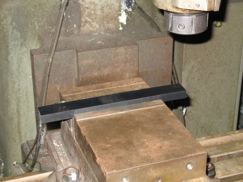
I'm going to start this project off with the feature that I haven't seen anyone else do yet - mounting an MCR320 in the top of the case. Stay tuned.
 

NicePants42

Partition Master
As you can see from the pictures in the first post, there is hardly any clearance between the BIP2 and the top edge of the motherboard - in order to make it fit the fans were mounted directly to the red Plexiglass top plate in order to not waste the ~3mm thickness of the case top plate.

In order to mount the thicker MCR320, I'm going to have to create more room, so I decided to use two Plexiglass plates this time, stacked one on top of the other - the top plate would serve to mount the fans and radiator, while the lower plate would simply act as a 3mm spacer to make everything fit. I also have to cut out more of the top of the case.

IMG_2064.jpg

I started with an clear AC Ryan Acrylpanel, taped it up and noted the width of the pieces I wanted. The pieces were cut out on a table saw - it only took two cuts because the 490mm x 490mm size turned out to be very convenient.

IMG_2068.jpg

Once the pieces were cut, the spacer plate was loaded onto a Bridgeport manual mill and covered with some scrap material to prevent chipping. Here you can see how it was cut out. I didn't do the milling here - I suggest that you be friendly to the people that you meet, one of them might be a machinist. Here you can see the finished piece.
IMG_2072.jpg

Notice that the bit still managed to jump around a bit on the top left corner. I have enough material to make another spacer, but I'll probably keep this one. Also notice that 6 holes were drilled to mount the panel to the top of the case. The previous build used 10-32 socket head cap screws to secure the top plate to the case, and M3 socket head cap screws to hold the fans/rad. Here, I plan to use black-oxide 6-32 button head cap screws to mount everything.

The next thing we did was mill out the top of the case. Due to the uni-body frame and the size of the Bridgeport's table, we got a little creative.
IMG_2073.jpg

IMG_2074.jpg

There is some scrap plastic material underneath the top of the case (white) and we made sure everything was clamped.

Milling:
IMG_2076.jpg

IMG_2077.jpg

Almost done.
IMG_2078.jpg

Finished. I didn't take enough pictures yesterday, but here's one I just took showing how the edges look.
IMG_2111.jpg

Since the fans will be mounted through the top of the case, they will completely cover the edging so I won't be painting it. The chip on the left is actually the remainder of one of the old mounting holes drilled by the previous owner.

The last item made yesterday was the top plate - all we used was a hole saw.
IMG_2079.jpg

IMG_2080.jpg

Looks pretty decent.

When I got home, I realized that I'd forgotten about the fan mounting holes on the top plate. Also, due to the limited table travel on the Bridgeport, I had to drill the top plate mounting holes into the case by hand. First I set everything where I wanted it and clamped.
IMG_2081.jpg

Then I just drilled through the top plate mounting holes through the case. In order to drill the fan mounting holes, I flipped to top plates over, set three fans into the opening in the spacer (which was now on top of the top plate), and drilled through the fan holes. Here's a test fit:
IMG_2087.jpg

Seems to work well. This next picture should clear up how these top plates are going to work.
IMG_2097.jpg

The three circular holes and fan mounting holes are in the top plate, whereas the wide rectangular opening is in the spacer plate underneath, so that the fans butt right up against the top plate, thus giving me another ~3mm of clearance for the MCR320. Tragedy struck when I untaped the spacer:
IMG_2096.jpg

I can remake the part, but I think I may be able to live with this. See, there are some mounting holes in the top of the case that need to be hidden - I'm planning to do this the quick and easy way - with a strip of electrical tape. I figure another strip on top of the spacer plate may go unnoticed.

But now it's time for the moment of truth - up until now I wasn't 100% sure that the radiator would clear the top edge of the motherboard. I did a quick test fit:
IMG_2086.jpg

IMG_2083.jpg

Concept Proven! MCR320 + 25mm fans fits with a 3mm spacer.

Then I opened up a box from Jab-tech....
 
Last edited:

NicePants42

Partition Master
Check these fans out.
IMG_2110.jpg

The top two fans here are Yate Loon -C fans, that I got from Jab-tech. They are only ~20mm thick, meaning that if I use these fans, the spacer plate is unnecessary. Unfortunately, the two that I received both made some fairly annoying noises while running. There's a rubbing sound that I don't like - Yate Loon isn't known for great QC, but for decent fans for little money. If it weren't for the noise and the fact that I've already made the spacer, I might've used these.

While I'm at it, here's a look at the BIP2, BIX2 and MCR320.

IMG_2103.jpg

This is the BIX2. It's fin density appears to be the same as the BIP2, but it's much thicker.

IMG_2105.jpg

Here's the BIP2. The BIP series is the thinnest that I'm aware of - mounting it without a spacer plate would be no problem. Don't be fooled by the spec thickness though, this thing is NOT 25mm thick overall. If you look at the technical drawing, you'll notice that the TANK is 25mm thick, but when I measure the mounting brackets, it's more like 28-29mm.

IMG_2104.jpg

And here's the MCR320 - fewer fins per inch means less fan rpm required to push through it, and with all the radiators I'm planning to stuff in this case, fewer rpms will be nice.

More to come next week.
 
Last edited:

madmat

Soup Nazi
Looks pretty good man. How thick is the plexi? I'm asking because if it's thick enough you could countersink the holes and use black socket bugle head machine screws and have the screws be flush with the plexi.

Also, do you know about flame polishing plexi? You expose a edge or hole (like countersinks) to a flame and it will gloss up like it was never cut. Just don't hold it there too long for obvious reasons. Two things about flame polishing... too long in one spot and it's over and after polishing do not expose it to alcohol or it'll shatter. Not into a million pieces but rather into a web of tiny cracks. It does do an awesome job though and with some experimentation you can make it look factory.
 

NicePants42

Partition Master
The plexi is 3mm thick. I'd considered using 5mm thick stock, but I didn't want to have a huge block of material on the top of the case. Also, as of right now I'm planning to use fan filters (the same ones I've used before) or a radiator grill. Either of these will sit on top of the plexi and neither will be thick enough to really accept a countersink.

As for flame polishing, I had initially planned on sanding, but if I can flame polish with a lighter, I may use this method to clean up my outer edges.
 

Merlin

The Tech Wizard
Man, THat's a lot of water. I guess you are not taking the case anywhere. Look's Great all lit up.
I'd like to see the temps when you get it all running

I'm running the CoolIt Freezone Chiller , temps are around 29C at idle and up to 40C at full load.

Merlin
 

Rob Williams

Editor-in-Chief
Staff member
Moderator
Looks great so far Nate! Looking forward to the progress. Sounds like it's going to be one heavy sucker when it's completed ;-)
 

NicePants42

Partition Master
Pump 'n Grind

Well, I didn't have much to do today, so I decided to try porting the two MCP655s I hope to use in this project. I think it went pretty well.

First, full credit for this mod goes to MartinM210. Martin has also been working on a very useful flow rate estimator that may help you pick components for your loop. One thing I had first considered doing was using two DB-1 pumps in series and only two MCR320s to build a near-silent system, but since I already have the MCP655s, and want to make the most of the space in the bottom of the case, I like my current plan. Silent is nice, but I'm going to try to use fan control in this system, and the MCP655s are adjustable.

Anyway, on to the pictures.

First, these are the two Dremel tools that I used to complete this modification (thus far).
IMG_2114.jpg


Here's the inside of the first MCP655 before the mod:
IMG_2118.jpg

The idea here is that the outlet needs to be smoothed out - there is a pretty big lip on it that needs to go, and things need to be more rounded in general. Here's how it looks now:
IMG_2120.jpg

You can tell I did this by hand :D
Most of the material was removed using the #104 cylindrical cutter head @ 6000-8000 rpm. I'd never done any of this before today, so it was a learning experience, but here's a general idea of how I'd do it:

1. Cut away the lip in the picture and start rounding the edge.
2. Once the entrance to the outlet is mostly flat, send the cutter head in through the outlet hole itself (making sure that it protrudes all the way into the inside of the housing) and open up the inside diameter.
3. Use the cutting head from the inside of the housing again to lean and round to the now slightly larger ID.
4. Clean up with the conical grinder (#7144).

I ran into trouble with my grinder because it's shaft was too small to lock snugly into my Dremel, so it slid in and out while running and thus I couldn't apply pressure in all the ways that I wanted. I think a circular or semicircular grinder or cutter would work better, so I may get one.

Here's the second pump before the mod:
IMG_2121.jpg

And after:
IMG_2122.jpg


The flash really emphasizes the scratching and I haven't cleaned out the chips yet, so they look a little rougher than they really are. Overall I'm pretty happy with how they came out; getting rid of the lip there should earn me most of the performance improvement I'm after, and the rounding is good enough.

I'm about to order some more parts that will be mounting in the bottom of the case. Later this week I should be able to figure out how I'm going to lay the components out.
 
Last edited:

Rob Williams

Editor-in-Chief
Staff member
Moderator
Looking good man! I wish I knew more about modding in general to offer some worthwhile insight, but I know nothing so I will just sit back and watch. :D
 

moon111

Coastermaker
Would one of those flexible dremel shafts of helped (how do I say this without dirty minds reading into this?) get your bit in deeper?
 

NicePants42

Partition Master
Would one of those flexible dremel shafts of helped (how do I say this without dirty minds reading into this?) get your bit in deeper?
I actually have one of these - it's used more for fine control (like while engraving) than for extending reach. I'd need the actual bit to have a longer shaft in order to get in through the outlet port.

I haven't been able to do much in the way of machining or assembly yet, but some new parts came in, and I'm getting a decent idea of how the lower compartment of the case will be laid out.

IMG_2150.jpg

First, I got a nice brick of 120mm fans. I'd spent some time testing various fans before deciding what to order for this build. I tried out a Sythe S-Flex Medium speed fan, and Enermax ENLOBAL fan, and a few different Yate Loon fans. I was very impressed with the quality and silence of the S-FLEX fan, but not impressed enough to spend $14 per fan. The ENLOBAL fan was quiet but also didn't move much air. In the end, I decided that Yate Loon Medium speed fans were the best combination of good airflow with low noise - a simple $12 Rheobus would add even more flexibility.

The thing with Yate Loons is that the quality is fairly variable - in this instance, I purchased 12 fans ($36!!) and took the time to listen to each of them on a Rheobus. I found that while all of the fans sounded great in the vertical position, 9 of the fans produced a noticeable rubbing noise when rotated to the horizontal position. Since I'll only have 3 fans mounted horizontally, this works out.

IMG_2151.jpg

I'm thinking of trying to mount the rheobus in the base, with the knobs sticking out the back.

IMG_2152.jpg

Here I've taped out the space in the base.

IMG_2157.jpg

The side with the triple radiator can easily fit one of the MCP655s in the back. The only trick here will be fitting the rheobus behind the pump.

IMG_2161.jpg

IMG_2162.jpg

The other side is going to be more cramped. Aside from dealing with the wiring (I'll be using a different PSU, but the dimensions are the same as the one pictures), the pump needs to be oriented in a somewhat funky manner, and it looks like this is going to push the radiator up towards the front slightly, meaning that up to 1" of fan surface may not line up with the side grills - something I was trying to avoid, but not a big deal.

IMG_2160.jpg

Top view. Mounting the pump will be fun.

IMG_2155.jpg

Here's about where the Multioption res will go - I'm not a fan of the new mounting brackets - clear is nice but the sharp edges will mark the clear tube. The tape in this picture marks the edge of the motherboard as well a line for a plate of aluminum which I'll use to mount the reservoir and hide some wires. It'll probably be at an angle -
IMG_2154.jpg

like this.

IMG_2163.jpg

I also got some copper fittings to help with the tube routing down there - it'll mean more connections and more hose clamps, but in this case it's going to be a necessary. Martinm210 has done some nice testing to show that the copper fittings result in the lowest pressure drop, so at least I know that I'm using the best 90-degree fitting solution here.

Hopefully I'll have more soon.
 
Last edited:

NicePants42

Partition Master
Ok, so apparently planning stuff out doesn't excite you people. How about some action?

We'll start with the easy stuff. I know I've seen this mod somewhere before - I'll link the log if I find it. EDIT: Found it. Anyway, here's that fan controller I said I was thinking about sticking in the base.
IMG_2165.jpg

That's about where it needs to go. I had originally thought that I'd just cut a clean sheet of black aluminum, drill some holes for knobs and mounting screws and replace the perforated back panel, but those heatsinks are going to need some air, so I decided to hack up the stock perforated panel.
IMG_2166.jpg

Here you can see where the knobs need to come through. Drilling through solid plate would've been easier than hacking through that perforated stuff, but this particular part of the mod isn't about being easy.
IMG_2174.jpg

After much drilling and dremelling, the holes are big enough to fit the knobs.
IMG_2175.jpg

IMG_2176.jpg

Ta-dah! 20 watts per channel of stealthed fan control, less the obnoxiously bright LEDs.

And now for the part you probably haven't seen before - that boring piece of tape at that boring angle...
IMG_2168.jpg

Plus a cheap piece of 6"x18" project aluminum from Lowes (they cut plexiglass to size!!)
IMG_2169.jpg

Held in place after a quick dremel cut to length.
IMG_2173.jpg

I cut a couple pieces of aluminum angle for mounting brackets.
IMG_2183.jpg

Held in place, drilled some holes, and attached the brackets to the plate with my trusty pop-rivet installer thingy. (I actually removed those rivets and cleaned the surfaces before installing new rivets to make sure that everything was flat.)
IMG_2180.jpg

Then it's just a matter of drilling mounting holes in the case for screws.
IMG_2184.jpg

And now I've got a nice removable panel there. The panel extends forward at an angle slightly past the rear of the front 5.25" mounting panel, so I bent the top a little and added another mounting screw to keep the thing from wobbling, seen here...
IMG_2195.jpg

..and here in the top right corner.
IMG_2187.jpg

At the top you can still see the blue tape that marks the edge of the motherboard. This plate should help to cover the wires up to that point pretty well. If the plate seems short, remember that the MCR320 in the top will be hanging down in there - it won't seem short then.

Here are a few views form the top.
IMG_2192.jpg

IMG_2193.jpg

IMG_2196.jpg

I'll probably still end up cutting the motherboard tray in order to more easily fit thicker hunks of cable (you can see that the main 20pin cable bends the aluminum plate), but this plate will help to hide any smaller (SATA, floppy) cables, as well as any holes.

Not only will this plate help to hide wires, it will also give me something to mount the reservoir to other than the motherboard tray. This way, I can remove the motherboard tray without removing the reservoir, which will help to reduce the hassle of changing out hardware. During assembly I'll try to make the most of this - I'm hoping to make it very easy to perform a hardware upgrade. ;)

And that about covers everything I've done thus far. This Saturday I hope to be able to machine some blocks to help mount the radiators at the right height, and that should just about do it for machining.

The problem I'm facing right now is availability of parts - Petras is out of several of the barbs I'd been planning to use, as well as the MCW60 + G80 adapter plate and D-tek Uni-sink. D-tek is supposedly releasing a new version of the Uni-sink by the end of the month. I'm also undecided on what motherboard to use - I was originally thinking I'd get the ASUS Blitz Formula (love that integrated watercooling) but considering my other parts issues and the fact that X38 will be released in ~ 2 weeks, I might just wait it out and get my old system running on air temporarily.

Anyway, hope you're enjoying the mod!
 
Last edited:

Rory Buszka

Partition Master
Wow, this is an incredible case mod that in my opinion really gets back to the original spirit of case modding. Back before every joe and jane could buy a pre-modded case with LEDs and bling, y0. The vertical milling part in particular is very cool. I don't really like working with plexi, though - cutting it on the table saw sends a shower of stinging melted plastic back at me. I don't think I even want to try using my router on the stuff, unless I want to make a dash to the ER with a broken wrist. I like those UV-sensitive orange fans you started with.
 
Last edited:

price0331

Obliviot
Wow, your quite outdoing what any above average joe would do here, very nice design and mod work. all ive ever done was change case lights haha.
 

NicePants42

Partition Master
Slow going mounting radiators, but the layout is plausible

First, you'll remember that my acrylic spacer plate for the top radiator got cracked. I believe that instead of the cracked plexiglass spacer plate, I am going to use nylon - since the spacer plate itself was covered with scrap nylon while being machined, we already had a nearly complete piece, and it took very little work to cut the scrap to the correct length and width. This spacer plate will not break as easily, is black, and is also 6mm thick instead of 3mm - something I wasn't sure would look good, but having looked at it, I'm satisfied.
IMG_2215.jpg

IMG_2216.jpg

IMG_2217.jpg

It also means I'll have another 3mm worth of space up top - while everything fit before, another 3mm ertainly won't hurt anything and will probably make it easier to route the CPU AUX power cable up there.


My work associate finished up the hard parts of the radiator mounts on Saturday.

Before I start explaining what I'm doing, let me say that in hindsight, I don't think mounts like these are necessary, and I've spent a lot of time doing manual drilling/tapping that may have been needless. In short, I'm sure that there's a better way to hold these radiators in the bottom of the case.

Anyway, in general we use right-angle something-or-other to hold radiators in place. I also need to raise the radiators ~1/2" off the base of the case to align the fans with the mesh openings in the side panels of the TJ07. I decided to use some (scrap) nylon as the base and add right-angle joints (cut from stock aluminum angle) to fasten the radiators.

First the nylon is machined.
IMG_2212.jpg

Notches were cut where the angle would be mounted, and holes were drilled to mount the nylon to the base of the case. Here you can see the notches and how they line up with the fan mounts. The nylon will be on the bottom of the radiator when installed.
IMG_2220.jpg

Here's the aluminum angle that was cut to length. It looks like ass compared to the machined nylon, but it'll never be seen.
IMG_2253.jpg

IMG_2251.jpg

IMG_2256.jpg

IMG_2257.jpg

In the last two pictures the holes have been drilled, and everything is mounted. I test-fitted with both side panels to make sure that there were no clearance issues. I tapped the holes in the nylon that hold the aluminum angle, and I tapped the holes in the bottom of the case that holds the entire assembly. My main problem was drilling holes in the aluminum that matched up with the fan screw holes on the inside of the radiator. I'm going to have to slop up these holes because I drilled them by eye, but I'm already using washers to attach them to the radiators, so it will work out. I'll also be adding some mounts to hold the radiators from the top, but I didn't get to those yet.

I had a problem when I tried to fit the Cooler Master Real Power Pro 1000 into the case - I found that it's mounting holes are oriented such that it can be mounted to the rear bracket, but then the bracket cannot be mounted to the case correctly. The hole locations on the PSU cause it to collide with either the bottom of the case or the top of the case (depending on how it's attached) so that the holes on the case and bracket don't line up. This may be able to be repaired by hand with a drill, but since the Bridgeport was working today anyway, I figured it'd be best to do it there.

Here's how the rear bracket looks now:
IMG_2243.jpg

IMG_2247.jpg

The mounting screws on the bracket fit in the lowest part of the machined holes. The aluminum in some spots is now pretty thin, so I used washers to help spread the load.
The PSU fits fine now.
IMG_2248.jpg


So, now that the PSU is mounted, I can get the pump in there and figure out where I need to drill the mounting holes.
IMG_2260.jpg

This pic isn't that great, but I've actually cut off several of the grips on the sides of the pump, decreasing it's overall diameter by ~3/8". This allows me to cram things together a little more so that I can keep the MCR220 lined up with the side grill opening, and clear of the front button pcb on the TJ07. I like this position better than the wacky orientation I was originally thinking would be necessary - this gives me more space between the MCR320 and the inlet (for tube bending), gives easy access to the speed controller and doesn't require any fancy mounting method.
In case anyone asks, those fins on the MPC655 are not for dissipating heat - they are there to make it easier to take the pump apart. The ring with the grips is actually a threaded retaining ring that holds the molded front inlet/outlet (which I worked on in post # 9) and motor together. It can be twisted off and on to disassemble/reassemble the pump.

I haven't taken many pictures this evening because most of my time has been spent drilling and tapping holes in the base of the case, and cutting a lot of screws to length. The layout is going to work well, although making all the tube connections might be a challenge.

Anyway, I'll be working on this more this coming week. There's more hardware on the way, so I hope it'll be interesting.
 
Last edited:

Merlin

The Tech Wizard
Okay...Okay...Now I want to build a mod

Man this is great....

I have an idea with a render farm box, using a humidifier enclosure.
I could get two computers into one box with plenty of cooling room.
This build you have going here is giving me ideas on the cooling of both computer in one case.
I'll get this into a cad program for blue prints.

Merlin
 

moon111

Coastermaker
Very interesting, can't wait to see this completed. I just bought some 120mm Yate Loon fans myself. They seem to be selling everywhere for an extremely low price. Haven't tested them.

Question, have you thought about rolling the edge of your cut panel? Fold 1/4" completely over, or bend that 1/4" to 90 degrees, place a wire in the crease then hammer the edge over. If done right, can make a nice edge.
 

NicePants42

Partition Master
Very interesting, can't wait to see this completed. I just bought some 120mm Yate Loon fans myself. They seem to be selling everywhere for an extremely low price. Haven't tested them.
After speaking to a couple people, I believe that the fans that I have are not genuine Yate Loon Fans. However, I could be wrong, and I did test a genuine Yate against these fans, and the noise difference was not noticeable.

Question, have you thought about rolling the edge of your cut panel? Fold 1/4" completely over, or bend that 1/4" to 90 degrees, place a wire in the crease then hammer the edge over. If done right, can make a nice edge.
I had considered chamfering the edge of the nylon panel to ~1/16" x 90 degrees with a cutter we have here specifically made for chamfering - but I actually think that it looks better as-is. I ran a utility blade along the sharp edge to break it. If I were able to modify the acrylic panel such that it's edges matched the nylon panel, I might do it, but for fear of breaking the acrylic I'm going to leave it alone.

Update to follow.
 

NicePants42

Partition Master
Mounting pumps and hacking up the fan controller some more

Due to the limited amount of time I have outside of work during the week, this update is going to be kind of scattered because I didn't work on any one thing very long.

Starting with the rear fan controller:
IMG_2265.jpg

Turns out that the top two heatsinks interfere with the pump placement. I know the pic isn't great, but the pump is sticking out of the case.

Since only a portion of the heatsinks were in the way, I decided to modify them a bit. I'll try to explain how to get them off.
IMG_2271.jpg

IMG_2272.jpg

In these two pictures you should be able to see that each heatsink has two tabs that stick through the board. These tabs are then twisted so that they cannot be pulled back through the pcb, and then the base of the pcb is covered in that foam stuff. Ignore the socks.

So, after unscrewing the heatsinks on top, I located the tabs on the underside through the foam by feel, then used a pair of needle-nose pliers to straighten them. From there a little pulling and twisting will dislodge them.
IMG_2269.jpg

Here's a closeup of one, where you can see the tabs in question.
IMG_2273.jpg

Having removed the heatsinks the pump now fits very well, and you can see that the rear-most portion of the heatsinks won't be a problem - so...
IMG_2282.jpg

IMG_2283.jpg

Snip! I actually removed a bit more from the top after another test fit.
Now, the plan is to cut a small sheet of aluminum and use solder to connect it to all 4 heatsinks (to share the load) and to the aluminum mesh panel (for more surface area). That part will probably be done when I start messing with the wiring (which will also require a solder iron).

So, knowing where the rear pump will fit allows me to mount it.
IMG_2280.jpg

I hold it in place, make pencil marks, and then clamp the pump base to get my hole locations.
IMG_2285.jpg

Slap on some gel-stuff from Petras...
IMG_2289.jpg

...and there it is.

Here's a shot from the inside looking back before the pump was mounted.
IMG_2276.jpg


As for the other pump, the holes were drilled in the same way, but...
IMG_2264.jpg

...they came out the bottom right where the material is at an angle. Oops. It might've been a problem if I had planned on having a bolt head or a nut down there, but instead I just tapped the holes and used mounting screws that don't stick all the way through.
IMG_2292.jpg

Mounted with more gel-stuff.

More to follow momentarily.
 
Last edited:
Top