raspberry pi anyone?

Tharic-Nar

Senior Editor
Staff member
Moderator
OK, so after a long wait for the software to mature on the RPi, a new distro has been released which takes advantage of some hardware acceleration. The Distro is a hard-float variant of Debian Wheezy called Rasbian - available on the RPi download page. You can read the official blog post here.

What's Changed?

After booting it up, first impressions are much better now. No longer are you dumped into a command-line with no idea what to do. There is even a configuration tool; so you can expand the SD card to make full use of available space, change regional settings for keyboard layout and timezone, and even change the memory commit ratio between the CPU and GPU.

The biggest changes though are the fact that hardware acceleration is now enabled. This means the GUI is much snappier than before. Compared to modern systems, this is still slow, but a huge leap compared to the soft-float builds previously. Web browsing via Midori is now practical. I've had multiple web pages open in various tabs, including some heavy hitters, and things have been running fine.

The default media player is now OMX, which I had to install manually in previous builds, so VLC is not required now. Additionally, the ALSA drivers now start up properly and won't need to be reinitialized every time you boot, however, all other problems regarding audio remain (can't switch tracks without stopping the previous, etc).

Overclocking...

One last thing I've been playing with is overclocking... yes, you can overclock the RPi. In the boot section of the image, there is a file called config.txt which is accessible even under Windows. Nearer the end of the file, you can set the default frequency of the RPi, but no other options are given. If you make a quick trip to the overclock page at elinux.org, you'll find a list of available options. Please note that a voltage adjustment will result in a hardware switch being set, voiding the warranty - however, pure frequency adjustments should be fine.

Reading through the forums, people have been reporting stable OCs of 1,000MHz with a minor voltage boost (base is 700MHz). The other interesting feature is that no heatsink is required (although, some are using them just in case). I'll try to run a few benchmarks later to compare the OC results. I'll also 'sacrifice' one of my unit's warranty and do some voltage tweaking too.

Nice to see things are moving along nicely.

Additionally, bulk orders are now available - and RPi in SPACE!!!
 
Last edited:

Tharic-Nar

Senior Editor
Staff member
Moderator
For those that don't know, the Raspberry Pi had a hardware revision, minor tweaks and some mounting holes, and swapping a couple pins round on the header board. More recently though, all new Model B Pis will come with 512MB RAM as standard.

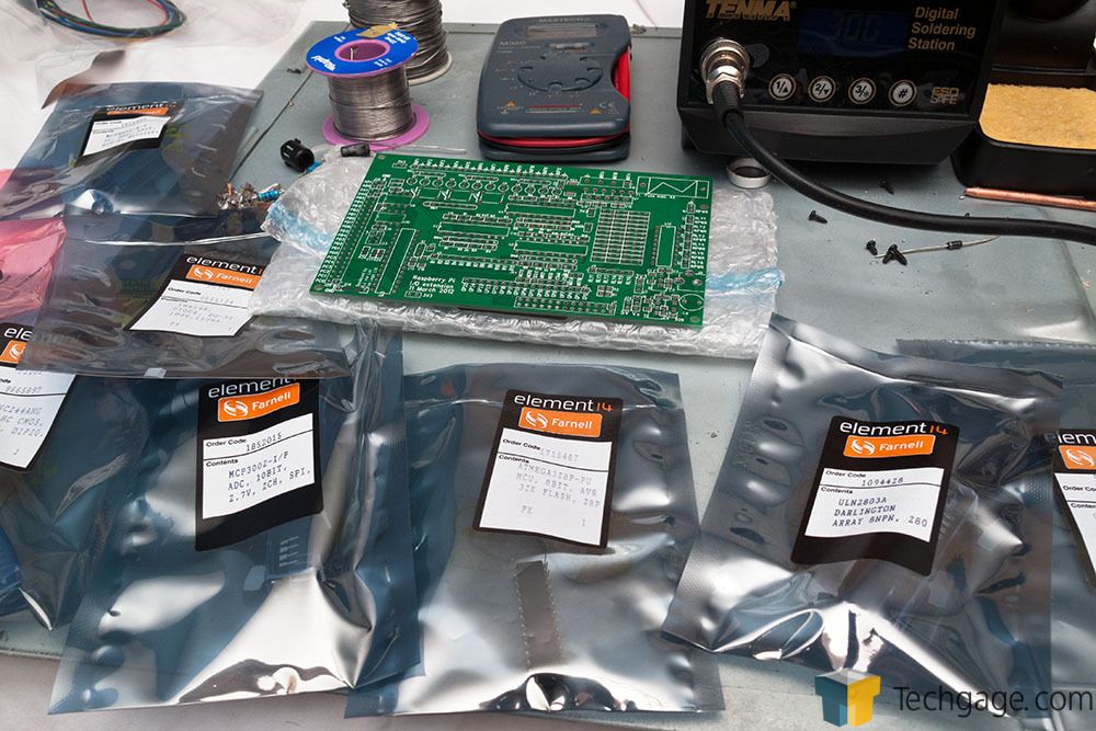
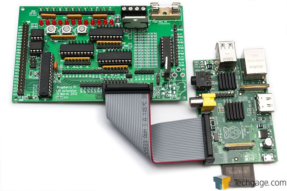
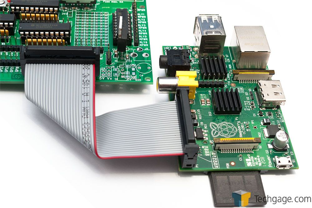
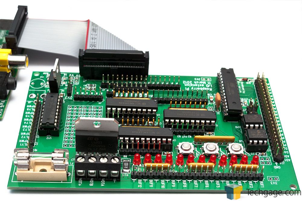
In other news Pi related, the Gertboard was shipped from Farnell/Newark to a load of people, myself included, and I've finished a two-hour soldering session with it. Let it be known that SMDs are a pain. For those that don't know, the Gertboard is an I/O expansion board for the Raspberry Pi, making use of the Pi's GPIO, I2C and SPI interfaces. The board comes with PWM, Motor Controller for servos or a stepper, there's some LEDs, push buttons, and last but not least, an ATMEGA328 microcontroller (like that found in an Arduino) for all those digital and analog I/O.

Anyway, I will be spending some time with it over the next few days, getting acquainted with it, and no doubt pulling out my hair in frustration, but who knows. Now like family slide-show, have a bunch of pictures of the assembly process. (The Gertboard comes as a kit only and requires assembly)

IMG_1236.jpg

Lots of bags to uncover.

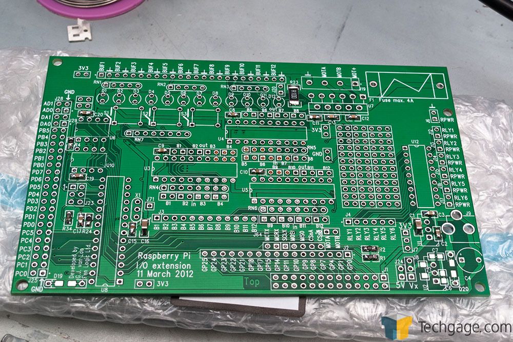
IMG_1238.jpg

The SMDs mounted - this took a fair bit of time for so few components. I don't have much experience with surface-mount, so it was an educational process.

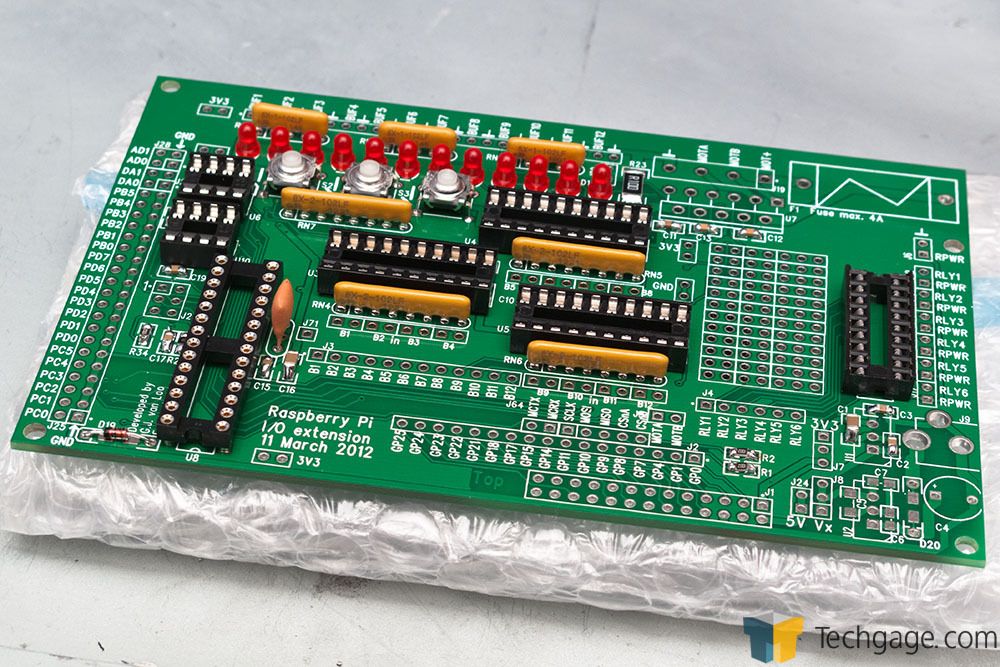
IMG_1240.jpg

Many of the larger components such as the resistor networks, LEDs, push-buttons and IC sockets soldered on.

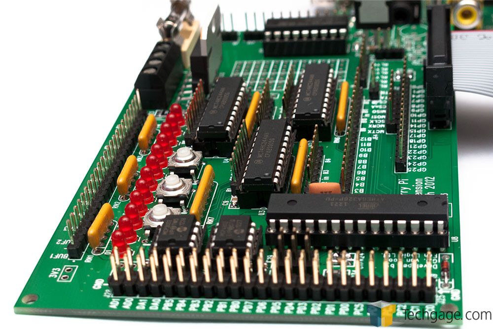
IMG_1244.jpg

The finished board with all the header pins and ICs inserted.

IMG_1242.jpg

This is to give you some idea of size compared to the RPi. The Gertboard is much larger due to the DIP sockets and more user-friendly assembly design.

IMG_1245.jpg

Yes, I put mini-heatsinks on the RPi for no real reason. They're not required for overclocking even (heat is not the limiting factor for a change).

IMG_1246.jpg

Another random shot of the assembled board.
 
Last edited:

Psi*

Tech Monkey
Nice work Thar, I have been thinking about numerous applications for this widget. Do you have particular "plans" or are you mostly into the moment at the moment & noodling it all out?
 

Tharic-Nar

Senior Editor
Staff member
Moderator
I do have plans, most of which are not terribly interesting at the moment since I'm still working out the kinks in the setup. I will say it involves a lot of sensors with data logging, later expanded into making use of the PWM features to control fans. However, I will stop to have some fun with a couple servos first. In the mid to long-term, I will need to build a sensor array and figure out how to handle all the inputs. I'm aware of multiplexers, but the problem remains signal amplification across different sensor types. I could use an instrumentation amp after the multiplexer, and then have a second multiplexer connected to the amp's feedback with multiple resistors to create a programmable variable gain - different gain levels for different sensor types. Before I really get Into all that though, I need to figure out exactly want I want to measure first, which is still changing.

Someone has done something similar, but with thermocouples only. In which case, they could get away with a single amp and MUX, since all the sensors were the same. But he did go that extra mile with a dedicated RealTimeClock and logger with LCD display - not sure I need that. My plan was to feed the results directly into the RPi, but that needs to stay connected online for the NTP reference (the RPi has no RTC).

Anyway, everything specific is still up in the air - first and foremost, I need to learn how to program the ATMEGA and fiddle with some thermistors, then figure out how to report the information to the RPi (and maybe log it) before really diving in the deep end with a MUX.

This is the main point of the board, to experiment and learn interfacing, as well as become familiar with microcontrollers. I do have an Arduino on the way (when it damn well arrives), so if the Gertboard can't do what I need it too at the same time, I have a backup. While the ATMEGA chip on the Arduino and the Gertboard are the same, the Gertboard has many of the pins already assigned functions, so total I/O available from the chip is reduced - there are also a bunch of jumpers that need to be set for specific purposes. The reason for all this is so that the board can be a jack of all trades and be educational, that's its primary purpose, rather than being a single large interface board.

There are a number of gotchas with the board though, the biggest one being that it's powered by the RPi. The RPi is already power limited, so you do have to be careful. There was originally a power input section on the Gertboard, the unused section in the bottom right corner. Gert decided to pull it from the final release due to heat issues, but there's nothing stopping us from re-implementing it. Anything more than a couple LEDs worth of power is likely to cause issue, so some kind of external power is recommended.
 
Last edited:

Psi*

Tech Monkey
Are you a C++ programmer? When I wrote code I never quite got into Linux, but am considering a re-visit. There is so much to pull together tho ... gcc or gnu cpp ... ugh, a little over whelming. I think I understand that code is uploaded to RPi from a PC?

I found it very easy to write device drivers in C++ tho; constructors/destructors were great for setting up DACs & ADCs, overloaded operators made writing (coding) projects straight forward and nearly self documenting. In other words I could look back over projects several months old & could still understand what it was supposed to do!
 

Tharic-Nar

Senior Editor
Staff member
Moderator
I am not a programmer, my experience is mainly limited to scripting and web-dev. The ATMEGA chips (Atmel AVR in general) is not C++ though, it's a C derivative (called Processing), so a little simpler, but more complex, depending how you look at it.

To be clear, the RPi IS a PC - it's just ARM based running Linux. It's not a micro controller, it's a full blown CPU. So I will be using the RPi as a full development environment to program the ATMEGA on the Gertboard. There are a mass of utilities and libraries ready to go, which I will slowly cover as I get the Gertboard singing and dancing - after I get a new multimeter in since mine has decided to read everything as 0, even after replacing the fuse (I need to confirm voltage regulation etc otherwise I could end up blow things up).
 

Tharic-Nar

Senior Editor
Staff member
Moderator
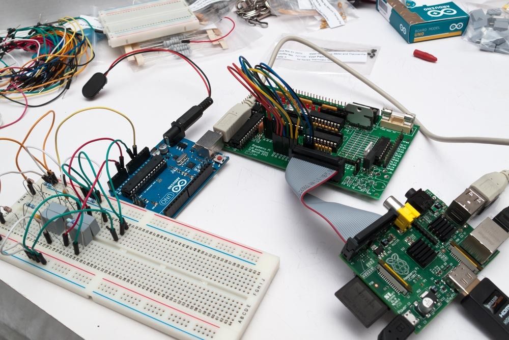
And things slowly get more complicated...

IMG_1259.jpg


Also, while testing out the Gertboard, I came across a rather weird problem. Stroking the GPIO cable would result in the various lights coming on. Think I made it self-aware...

<object width="420" height="315"><param name="movie" value="http://www.youtube.com/v/ZoB75RGA8ME?version=3&amp;hl=en_GB"></param><param name="allowFullScreen" value="true"></param><param name="allowscriptaccess" value="always"></param><embed src="http://www.youtube.com/v/ZoB75RGA8ME?version=3&amp;hl=en_GB" type="application/x-shockwave-flash" width="420" height="315" allowscriptaccess="always" allowfullscreen="true"></embed></object>
 

Psi*

Tech Monkey
hahaha ... sweet ... impressive effort.

You have an electrostatic personality. Or, possibly more likely, the circuit is influenced by your body capacitance.
 

Tharic-Nar

Senior Editor
Staff member
Moderator
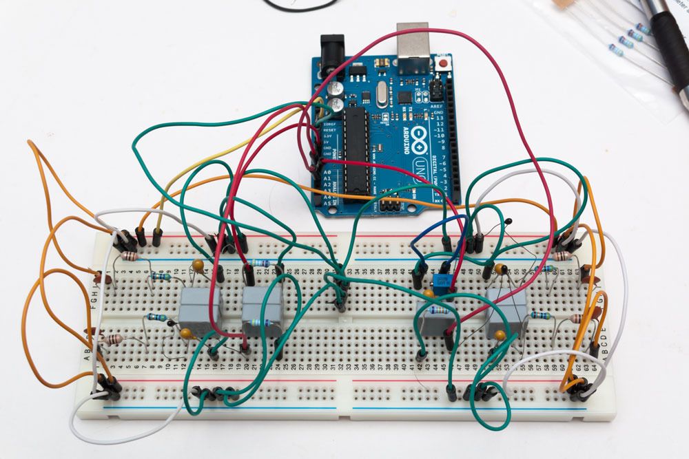
Yeah, I have no idea what to make of it honestly. Not going to say my soldering is perfect... but I'm having a hard time trying to figure out what's going on. Regardless, I've been moving on with other things and have multiple thermal sensors boarded out. All the thermistors are 50kOhm - there are several reasons for this rather than the standard 10k. First, minimise any self-heating effect. Second, the temp range I will be dealing with is not the 0-30C range that 10ks are built for. Third, price.... the 50Ks were cheaper than the 10ks at the time.

Although hard to see, the thermistors are the tiny black dots with long spindly legs. Later, I will be trimming them down and using some speaker wire to give them some range as well as insulate them.

On the left side of the board, there are two thermistors hooked up like a voltage divider to a 49k9 0.1% 15ppm resistor. This gives the thermistor something like a 0.2C accuracy envelope in the 30-60C range (1% accumulative accuracy outside this envelope). The bottom right sensor has a 133k 0.1% 15ppm resistor, this moves its accuracy envelope to the 60-120C ish range (not entirely sure). The top right sensor has a multi-turn 1M preset pot which I can tune to whatever level I want. It's only 10% accurate or so and will likely be affected quite a bit by temp, but it's an experimental probe for when I want a different range. All the probes are on RLC filters, with an additional decoupling on the fixed resistor. (The Arduino uses a switcher supply, so it'll be noisy, not something I want when dealing with a precision sensor.)

I could have gone with thermocouples, but the more I read into them, the worse I felt about using them - +/-1.5C on a good sensor, plus extra interference with all the other circuits in the way leading to a 2.5C margin of error? Pass...

When I originally laid out the board, the two probe arrays were feeding off each other, so I was seeing 25k on the 49k9 resistors. Putting a 100n cap at the beginning of each power input fixed all that (which will likely introduce another problem later).

IMG_1263.jpg


Anyway, that's four probes going to four inputs on the Arduino (which has a 10bit ADC), and now I'm just trying to get it to behave and read the temps reliably with some crazy maths (Steinhart-Hart coefficients) which I stole from other people. They just need tweaking for the values I will be using. Once I can read one sensor accurately as a function, I can then call on it for each sensor. Once all that is done, I can then move onto multiplexing - providing I have enough memory on the ATMEL.
 
Last edited:

Tharic-Nar

Senior Editor
Staff member
Moderator
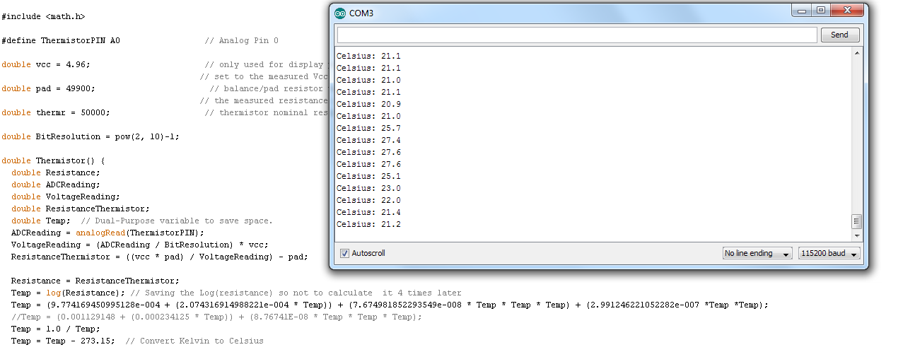
So I ran into complications, (as one does), an incorrect resistor (47Ohm instead of 49K9) and the wrong coefficients derived from an incorrect thermistor model number, plus a lot of mucking around in the Arduino IDE - I managed to (finally) get one of the thermistors reading temps, and very accurately I might add. Using existing code examples gave my either horribly results (600+ or -100C), or failed to compile (I have no clue when it comes to programming). After a few hours of fudging with maths, bad code and an incorrect resistor... I have this!

WOOT.png


Yeah, so not that impressive... but I'm getting there. Next step, creating a function and then calling on it for different sensors and configurations and outputting the results simultaneously.

Once I clean up the code, I'll write up what I did.
 
Last edited:

Tharic-Nar

Senior Editor
Staff member
Moderator
At the moment, it's windows because handling all the reference research would be a little too much on the RPi at the moment. However, the Arduino IDE is multi-platform, it doesn't matter where I write the code, it behaves the same - I'll load it up on the RPi and you can see for yourself. The compiler is the IDE too - albeit rather simple in nature.
 

Tharic-Nar

Senior Editor
Staff member
Moderator
For posterity, here's the code I used. It was heavily based on the Thermistor2 Sketch, but extended, plus some help from the Thermistor4 Sketch, as detailed in this new Sketch. It uses the full equation, also changed some of the variables to make them clearer (for me) to understand.

For clarity, "#include math.h" should include < and > around math.h - HTML bug.

Code:
/*
 * Inputs ADC Value from Thermistor and outputs Temperature in Celsius
 *    requires: include math.h
 * Utilizes the full Steinhart-Hart Thermistor Equation:  [url]http://en.wikipedia.org/wiki/Steinhart-Hart_equation[/url]
 *    Temperature in Kelvin = 1 / {A + B[ln(R)] + D[ln(R)]3 + C[ln(R)]2}
 *    where A, B, C, and D are the Steinhart-Hart coefficient constants
 *
 * If your thermistor manufacturer does not provide these constants, they can be calculated from [url]http://thermistor.sourceforge.net/[/url]
 * You will need at least a basic Resistance/Temperature table for your thermistor (minimum of 3 values).
 * These tables are often found in the datasheet for your particular model.
 * This example uses ATCSemitech SP series Thermistors. Model: 503SP-*050
 *
 * Enter R/T values into the simu.txt file then run coeff.exe to generate the individual coefficients.
 *
 * Thermistor Schematic:
 *   [Ground] -- [fixed resistor] -- | -- [thermistor] -- [Vcc (5 or 3.3v)]
 *                                   |
 *                              Analog Pin 0
 *
 * For best accuracy, measure Voltage and the Fixed Resistor, do not assume values are absolute (5.00V and 50Kohm exactly)
 * To minimise self heating effect, use a higher resistance thermistor.
 * If using a noisy power supply (switcher) decoupling may be required.
 *
 * This Sketch was heavily based on the Thermistor2 sketch by Milan Malesevic and Zoran Stupic
 * [url]http://www.arduino.cc/playground/ComponentLib/Thermistor2[/url]
 * The full Steinhart-Hart equation, related material and implementation was based on Thermistor4 by MODAT7
 * [url]http://www.arduino.cc/playground/ComponentLib/Thermistor4[/url]
 *
 */

#include math.h

#define ThermistorPIN A0                 // Analog Pin 0

double InputVoltage = 4.96;              // Measure input voltage for accuracy.
double Rfixed = 49900;                   // Fixed resistor value for voltage divider, measure for accuracy. Stated in ohms
double ThermistorResistance = 50000;     // Thermistor nominal resistance @25C, used for reference and not calculated. Stated in ohms
double BitResolution = pow(2, 10)-1;     // ADC resolution, Arduino = 10bit

// The following are the idividual Steinhart-Hart coefficients used in the equation below, labeled as A, B, C and D
float ShHA = 9.774169450995128e-004;
float ShHB = 2.074316914988221e-004;
float ShHC = 2.991246221052282e-007;
float ShHD = 7.674981852293549e-008;

double Thermistor() {
  double ADCReading;
  double VoltageReading;
  double ResistanceThermistor;
  double Temp;                                                                               // Dual-Purpose variable to save space.
  
  ADCReading = analogRead(ThermistorPIN);                                                    // The reported value of the raw Analog Input.
  VoltageReading = (ADCReading / BitResolution) * InputVoltage;                              // Sets the voltage scale as per ADC resolution.
  ResistanceThermistor = ((InputVoltage * Rfixed) / VoltageReading) - Rfixed;                // Voltage divider, between fixed and thermistor.
  Temp = log(ResistanceThermistor);                                                          // Temporary, so not to calculate it 6 times later.
  Temp = (ShHA + (ShHB * Temp)) + (ShHD * Temp * Temp * Temp) + (ShHC *Temp *Temp);          // Steinhart-Hart Equation.
  Temp = 1.0 / Temp;                                                                         // Inverted equation to provide temperature in Kelvin
  Temp = Temp - 273.15;                                                                      // Convert Kelvin to Celsius                      

  // Uncomment to show Debug Information
  //Serial.print("ADC: "); 
  //Serial.print(ADCReading); 
  //Serial.print("/1024");                           // Print out raw ADC number
  //Serial.print(", vcc: ");
  //Serial.print(InputVoltage,2);                    // Input Voltage
  //Serial.print(", Fixed Resistor: ");
  //Serial.print(Rfixed/1000,3);                     // Value of Fixed Resistor
  //Serial.print(" Kohms, Volts: "); 
  //Serial.print(VoltageReading,3);                  // Voltage across divider
  //Serial.print(", Voltage Divider: "); 
  //Serial.print(ResistanceThermistor);
  //Serial.print(" ohms, ");

  // Uncomment this line for the function to return Fahrenheit instead.
  //temp = (Temp * 9.0)/ 5.0 + 32.0;                // Convert to Fahrenheit
  return Temp;                                      // Return the Temperature
}

void setup() {
  Serial.begin(115200);                             // Display over serial interface at 115200 baud
}

void loop() {
  double temp;
  temp=Thermistor();                                
  Serial.print("Celsius: "); 
  Serial.print(temp,1);                             // display Celsius
  //temp = (temp * 9.0)/ 5.0 + 32.0;                // converts to  Fahrenheit
  //Serial.print(", Fahrenheit: "); 
  //Serial.print(temp,1);                           // display  Fahrenheit
  Serial.println("");                                   
  delay(5000);                                      // Delay in ms
}
 
Last edited:

Tharic-Nar

Senior Editor
Staff member
Moderator
Yes, they are both the same, it's just that floating points in general are technically slower and with only 6-7 digits of precision, so it makes no difference.

http://www.arduino.cc/en/Reference/Float
http://www.arduino.cc/en/Reference/Double

Floating-point numbers can be as large as 3.4028235E+38 and as low as -3.4028235E+38. They are stored as 32 bits (4 bytes) of information.

Floats have only 6-7 decimal digits of precision. That means the total number of digits, not the number to the right of the decimal point. Unlike other platforms, where you can get more precision by using a double (e.g. up to 15 digits), on the Arduino, double is the same size as float.

There is an exception...
On the Arduino Due, doubles have 8-byte (64 bit) precision.

So I might as well switch all values with the coeff to double.
 
Last edited:

marfig

No ROM battery
Indeed. Double is a better bet given the circumstances. In fact, with or without the Aruino Due, unless you don't really need the extra precision and you are fine with 7 precision for < 1 and 6 precision for > 1, it's an almost guarantee that future iterations of the Arduino will come sooner or later with proper double precision-floating point.
 

Tharic-Nar

Senior Editor
Staff member
Moderator
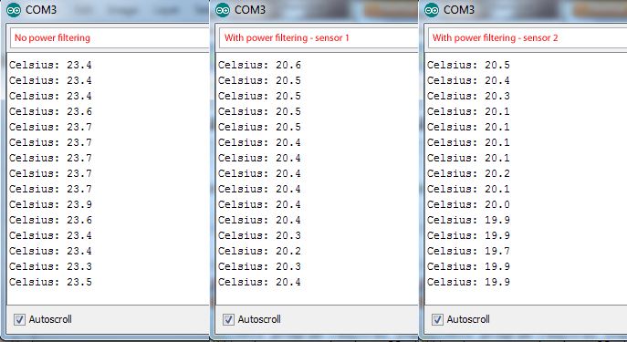
I've been switching things around on the hardware side. I decided to see the impact of power filtering. It's not a clear cut, but the irregularity of the sensor is noticeable - it can 'scatter' by 0.5 degrees in either direction. With filtering, it's a lot more incremental, steady steps. I then swapped the sensor into a filtered circuit and check, and noticed a steady temperature set. I then swapped the thermistor for a different one to confirm values. There is a 3.0C offset between the filtered and unfiltered, likely the result of a voltage or resistor value inaccuracy. I'll need a larger sample bin though to call it, but those swings in temp are not good...

thermistor_comparison.png


Actually, looking at it... filtered sensor2 is not that great either... Yeah, I think I need to find a more stable environment. Me being half a meter away is causing the temp to spike in places (damn the thing is sensitive...).
 
Last edited:

marfig

No ROM battery
I wonder...

You said a few days ago that one of the reasons you didn't choose the 10KOhm thermistors was because you wouldn't be operating at their 0-30C range. However that's exactly what I'm seeing there. Wouldn't it be better to indeed go with the 10K?

Also, but here I'm not sure... aren't the 50K just a tad bit more power hungry? Wouldn't it affect your readings? I'd expect them to increase temps slightly as opposed to a 10K.
 

Tharic-Nar

Senior Editor
Staff member
Moderator
Higher resistance means less power going through the probe (the tighter the valve, the less water that can flow). The sensors I have are 0.2C accurate between 0-70C. I re-read an article to make sure things are fine, and they should be. Its reference 50k probes, going by the graph, are good between 10 - 110C, while a 10k probe is good for -20 - 70C. So my probe should be more than adequate in the room-temperature range. I could get in some 10K sensors too, but I'm likely to see similar results, but with more swing due to the extra sensitivity.

http://www.embeddedrelated.com/showarticle/91.php

I'll retest things later in a more controlled environment (no fans going, closed door) with multiple sensors, and measure the fixed resistor properly on the unregulated board - and run the test longer too. But even if I am in the lower end of the recording accuracy range based on the manufacturer and by that general graph - I still think things should be fine. These sensors will end up in a PC environment, so will likely see temps in the 30-40C ambient range, going up to 60-90C next to the CPU. The variations I'm seeing are in the 0.2-0.5C range (which coincides with natural room fluctuations + sensor error or 0.2). The 3 degree hike on the unregulated board still has my concern, but I need to look into that carefully.

Edit: I should probably just add an averaging system - 10 readings over a couple seconds, then averaged.
 
Last edited:
Top