I am not an audiophile, but I do enjoy listening to quality audio. For a while now I've been eyeing up an amp so that I'm not limited to my sound card for driving headphones. The majority of soundcards do not have amplifiers in them, so when plugging in high impedance headphones, the volume is often limited and can sound rather muddy - this is when an amp comes in handy.
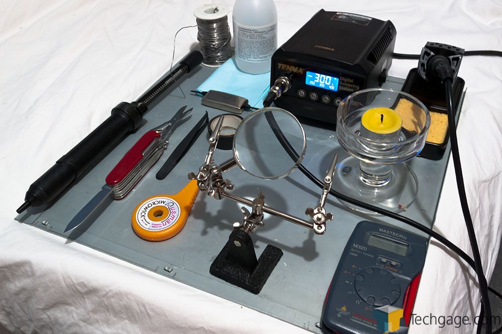
There are a lot of cheap amps out there ($40-$50) and pretty much all of them just make things louder with little regard to clean signal paths, often resulting in noise from the power input. However, it's possible to improve these low end amps and turn them into something a little more appealing. So thus was born the perfect excuse to break out the soldering kit and experiment.
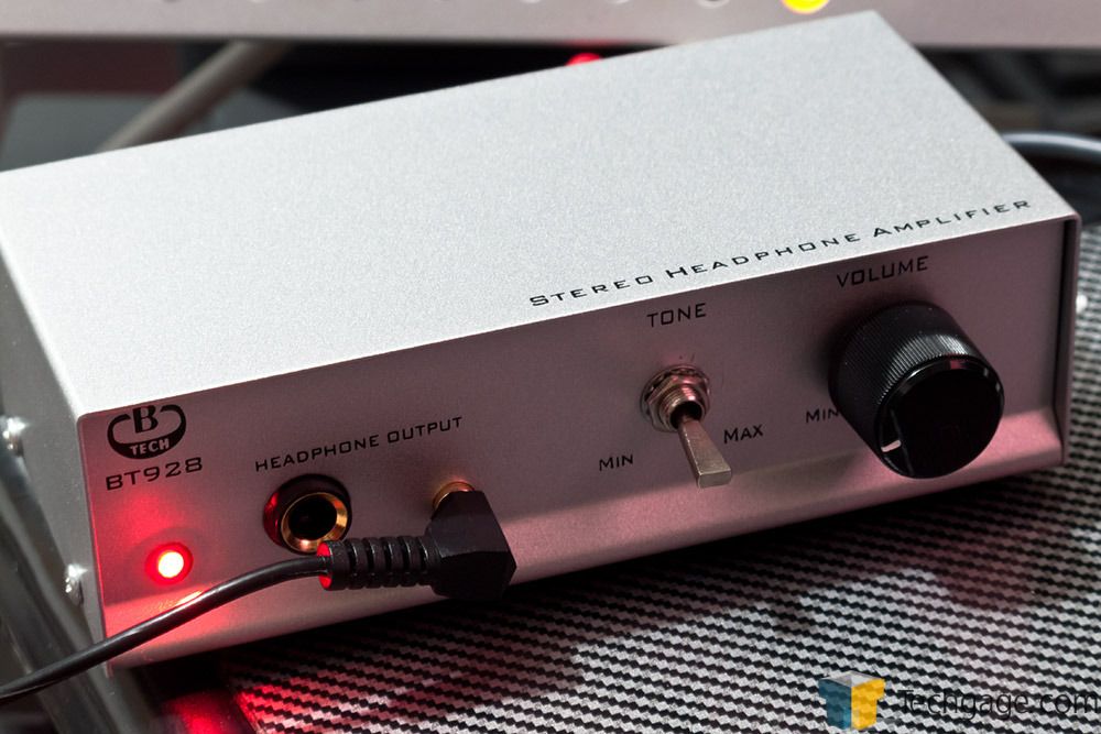
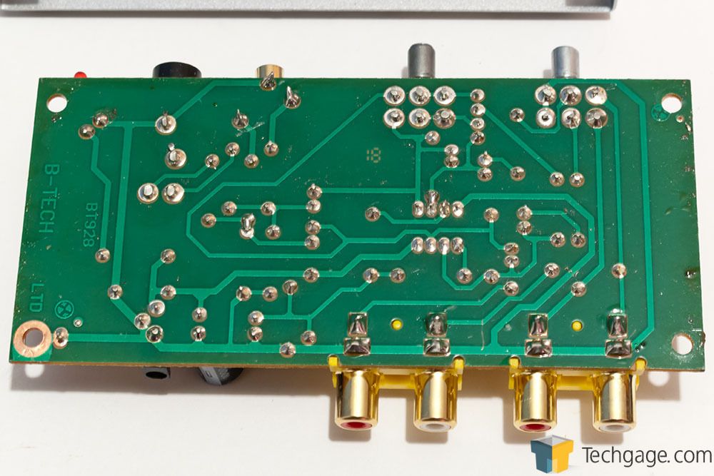
The amp I bought in was the B-Tech BT928 Stereo Headphone Amplifier. This particular model is quite cheap and well known for being modded. I won't be doing anything new, the following mod is quite straight forward and well documented as the 'PinkFloyd' mod. So let's have a look at what's involved.
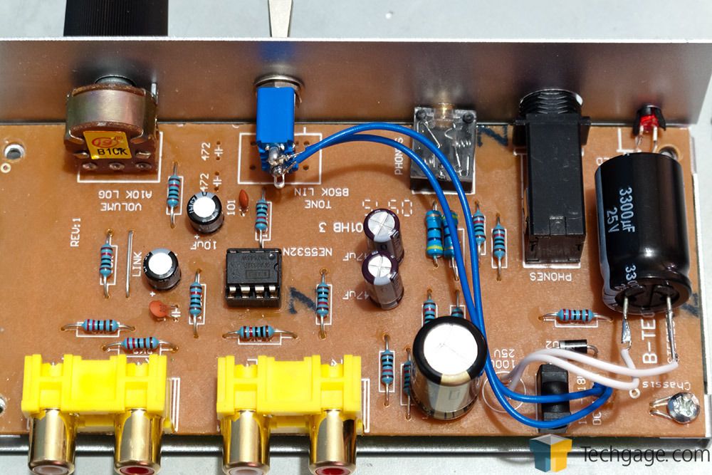
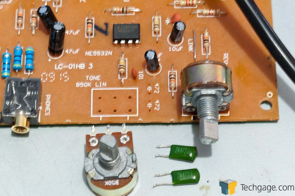
The first thing to be done, and perhaps the most critical, is the removal of the tone control (50k potentiometer). By default, this works as means of suppressing high frequencies, but in reality all it does is destroy detail and makes everything sound washed out and muddy, even with it 'off' (max). Removing it and the two adjacent green capacitors effectively allows for the full signal to pass through unaltered (sort of).
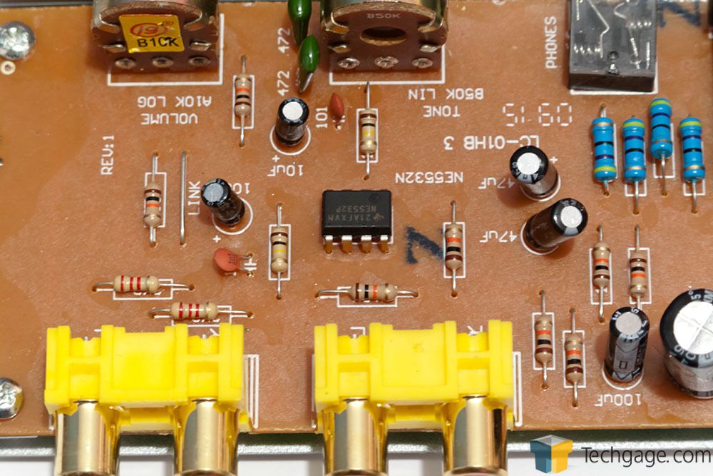
The next step is to change the op-amp. The NE5532N included is 'good enough', but it's always nice to have something with a little more character. Choosing an op-amp to replace it with is pretty much trial and error; to prevent future headaches, an 8pin DIP socket is mounted instead of resoldering each time. The op-amp I went with to begin with was a Texas Instruments (Burr-Brown) OPA2132. I could have gone with an OPA2134, an OPA627 is about three times the price, and an Analog Devices AD843 is about twice the price of the OPA2132. So as time goes on and I get a better pair of headphones, I may switch op-amp.
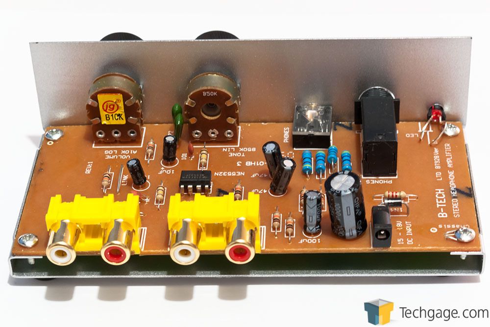
With the op-amp replaced, it's time for the big one - switching all the capacitors out for something in the quality bracket (subjective of course). Supposedly for audio, the best caps are low impedance (ESR) with a high AC current ripple. I didn't know exactly what I was looking for at the time I got these caps in, so I will be switching these again later for some Panasonic FR and FC type electrolytic. For now, I am using HD series (high endurance).
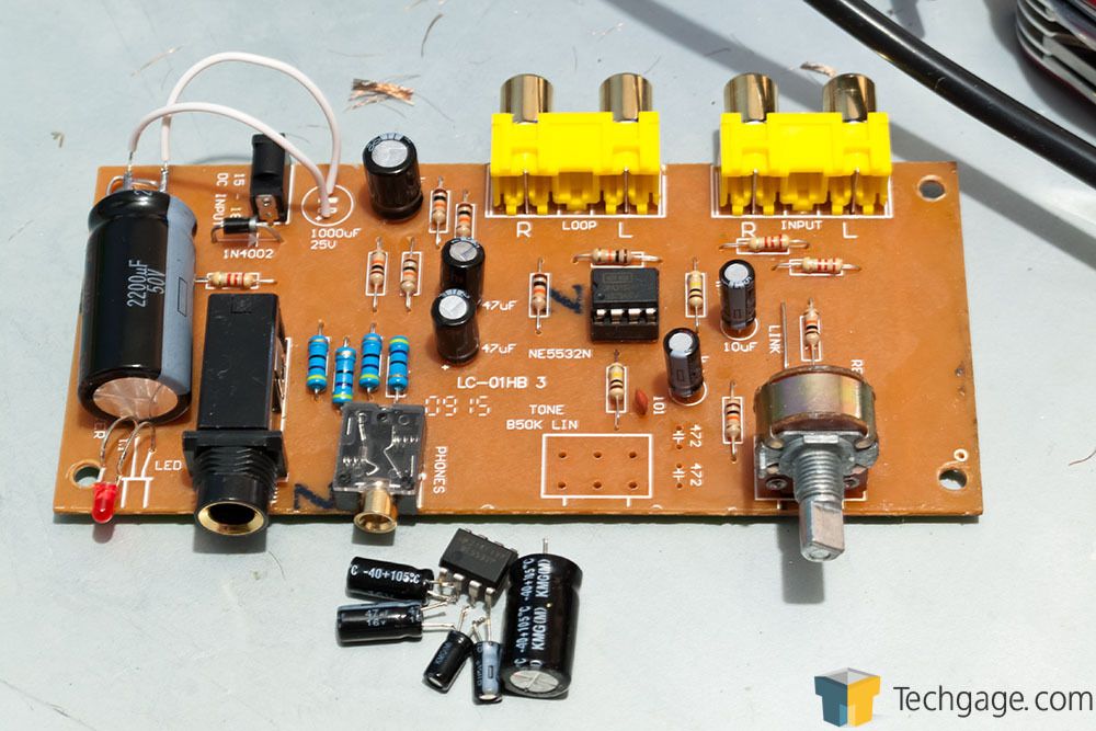
The 16v 1000uF cap next to the power input was replaced with a 50v 2200uF. The rest remained as their respective 100uF, 47uF and 10uF - each replaced with a 50v higher grade cap. Why 50v? Because they were cheap at the time and as long as the cap is equal to or exceeds the input voltage, it doesn't matter (higher rated voltage also increases the lifespan of the cap too). Well, this is what I'm told . With all said and done, the board looked like this afterwards.
So what did $15 of parts and some soldering do to the quality? Quite a lot actually. First of all, I'm only using a pair of Corsair HS1As at the moment, but even with these I can tell the difference. I will go through each mod and try and explain the differences in sound quality. This is subjective to an extent of course.
With the base unit, the tone control really does get in the way and is only good for killing high frequencies. General quality is rather low in general, coming from a direct input on the ASUS Xonar DX. There was a fair bit of noise on the line, so power filtering would be recommended. The unit comes with a 15v basic DC adapter. Getting a regulated supply would be beneficial. The unit can drive up to 200 Ohms impedance, so it's a lot more powerful than the soundcard.
Removing the tone control immediately released all those suppressed higher frequencies, but there was still noise on the line. Bass frequencies were not that punchy either, but things did improve.
Replacing the op-amp didn't actually have a huge impact. Noise was still on the line, but there was greater clarity in the mid-high range, but started to become borderline tinny.
Replacing the caps made a massive difference. Most of the noise had gone at this point. There is a little bit of click-based rumble, so further filtering is required either on the DC input or via better caps. The big change in audio quality though was a further increase in clarity, but also bass response became a lot more punchy and sharp. This is in fact much improved over what the Xonar DX could do by itself, despite the HS1A's being low impedance. Making EQ adjustments confirmed this and bass became much more alive without blowing out the mid-range. Bear in mind, these caps are not really that great for audio (technically), so when they get replaced with the FR and FC range, it should prove interesting what further improvements can be made.
Overall, the amp has become more powerful too, as I need to set the volume lower compared to stock. The last thing to bear in mind though is burn-in. I've only had the amp for about 10 hours and it'll probably take a week for the caps and op-amp to settle (quite common for audio equipment). So I'll see how things go in the future. Maybe the noise will clear up...
So what's next?
Later I will be fitting a switch so I can turn the amp on and off on the box, since it's always live when plugged in. I will also be switching out the volume control potentiometer too, since if I'm honest, is rather poor (imbalanced channels at different volumes, e.g. left channel can be louder than the right at on point, then even out as you go higher). The caps will be changed too at a later date (next month most likely).
So if you fancy a headphone amp and want to scratch that modding itch, this is definitely something worth trying - if you have the need and on a budget.
There are a lot of cheap amps out there ($40-$50) and pretty much all of them just make things louder with little regard to clean signal paths, often resulting in noise from the power input. However, it's possible to improve these low end amps and turn them into something a little more appealing. So thus was born the perfect excuse to break out the soldering kit and experiment.
The amp I bought in was the B-Tech BT928 Stereo Headphone Amplifier. This particular model is quite cheap and well known for being modded. I won't be doing anything new, the following mod is quite straight forward and well documented as the 'PinkFloyd' mod. So let's have a look at what's involved.
The first thing to be done, and perhaps the most critical, is the removal of the tone control (50k potentiometer). By default, this works as means of suppressing high frequencies, but in reality all it does is destroy detail and makes everything sound washed out and muddy, even with it 'off' (max). Removing it and the two adjacent green capacitors effectively allows for the full signal to pass through unaltered (sort of).
The next step is to change the op-amp. The NE5532N included is 'good enough', but it's always nice to have something with a little more character. Choosing an op-amp to replace it with is pretty much trial and error; to prevent future headaches, an 8pin DIP socket is mounted instead of resoldering each time. The op-amp I went with to begin with was a Texas Instruments (Burr-Brown) OPA2132. I could have gone with an OPA2134, an OPA627 is about three times the price, and an Analog Devices AD843 is about twice the price of the OPA2132. So as time goes on and I get a better pair of headphones, I may switch op-amp.
With the op-amp replaced, it's time for the big one - switching all the capacitors out for something in the quality bracket (subjective of course). Supposedly for audio, the best caps are low impedance (ESR) with a high AC current ripple. I didn't know exactly what I was looking for at the time I got these caps in, so I will be switching these again later for some Panasonic FR and FC type electrolytic. For now, I am using HD series (high endurance).
The 16v 1000uF cap next to the power input was replaced with a 50v 2200uF. The rest remained as their respective 100uF, 47uF and 10uF - each replaced with a 50v higher grade cap. Why 50v? Because they were cheap at the time and as long as the cap is equal to or exceeds the input voltage, it doesn't matter (higher rated voltage also increases the lifespan of the cap too). Well, this is what I'm told
. With all said and done, the board looked like this afterwards.
So what did $15 of parts and some soldering do to the quality? Quite a lot actually. First of all, I'm only using a pair of Corsair HS1As at the moment, but even with these I can tell the difference. I will go through each mod and try and explain the differences in sound quality. This is subjective to an extent of course.
With the base unit, the tone control really does get in the way and is only good for killing high frequencies. General quality is rather low in general, coming from a direct input on the ASUS Xonar DX. There was a fair bit of noise on the line, so power filtering would be recommended. The unit comes with a 15v basic DC adapter. Getting a regulated supply would be beneficial. The unit can drive up to 200 Ohms impedance, so it's a lot more powerful than the soundcard.
Removing the tone control immediately released all those suppressed higher frequencies, but there was still noise on the line. Bass frequencies were not that punchy either, but things did improve.
Replacing the op-amp didn't actually have a huge impact. Noise was still on the line, but there was greater clarity in the mid-high range, but started to become borderline tinny.
Replacing the caps made a massive difference. Most of the noise had gone at this point. There is a little bit of click-based rumble, so further filtering is required either on the DC input or via better caps. The big change in audio quality though was a further increase in clarity, but also bass response became a lot more punchy and sharp. This is in fact much improved over what the Xonar DX could do by itself, despite the HS1A's being low impedance. Making EQ adjustments confirmed this and bass became much more alive without blowing out the mid-range. Bear in mind, these caps are not really that great for audio (technically), so when they get replaced with the FR and FC range, it should prove interesting what further improvements can be made.
Overall, the amp has become more powerful too, as I need to set the volume lower compared to stock. The last thing to bear in mind though is burn-in. I've only had the amp for about 10 hours and it'll probably take a week for the caps and op-amp to settle (quite common for audio equipment). So I'll see how things go in the future. Maybe the noise will clear up...
So what's next?
Later I will be fitting a switch so I can turn the amp on and off on the box, since it's always live when plugged in. I will also be switching out the volume control potentiometer too, since if I'm honest, is rather poor (imbalanced channels at different volumes, e.g. left channel can be louder than the right at on point, then even out as you go higher). The caps will be changed too at a later date (next month most likely).
So if you fancy a headphone amp and want to scratch that modding itch, this is definitely something worth trying - if you have the need and on a budget.